AUTOMATIC TRANSMISSION UNIT DISASSEMBLY

-
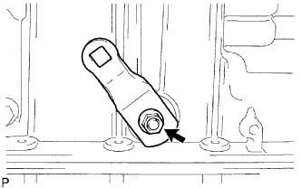
REMOVE TRANSMISSION CONTROL SHAFT LEVER LH
-
Remove the nut, washer and control shaft lever LH.
-
-
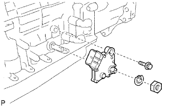
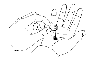
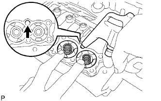
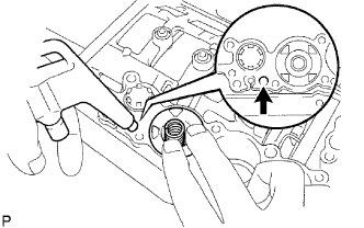
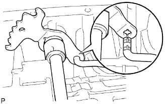
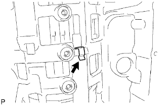
REMOVE PARK/NEUTRAL POSITION SWITCH ASSEMBLY
-
Using a screwdriver, pry out the lock washer.
-
Remove the nut, lock washer and bolt.
-
Remove the park/neutral position switch.
Tech Tips
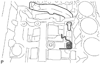
Make sure that the manual valve lever shaft has not been rotated prior to installing the park/neutral position switch as the detent spring may become detached from the manual valve lever shaft.
-
-
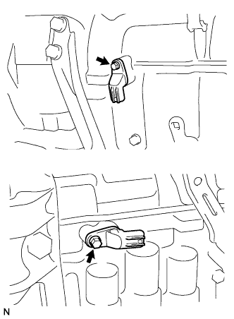
REMOVE OIL COOLER TUBE UNION
-
Remove the 2 oil cooler tube unions.
-
Remove the O-ring from the oil cooler tube union.
-
-
REMOVE SPEED SENSOR
-
Remove the 2 bolts and 2 transmission revolution sensors.
-
Remove the O-ring from each sensor.
-
-
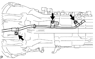
REMOVE AUTOMATIC TRANSAXLE BREATHER TUBE
-
Remove the 3 bolts.
-
Remove the breather tube.
-
Remove the O-ring from the breather tube.
-
-
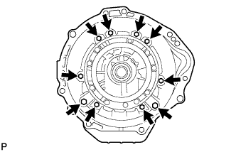
REMOVE AUTOMATIC TRANSMISSION HOUSING
-
Remove the 10 bolts.
-
Remove the transmission housing.
-
-
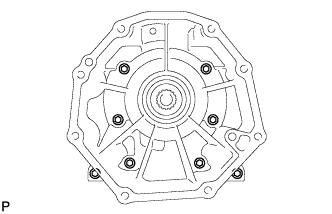
REMOVE TRANSMISSION CASE ADAPTER SUB-ASSEMBLY
-
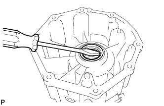
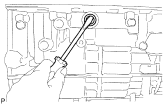
REMOVE TRANSMISSION CASE ADAPTER OIL SEAL
-
Using a screwdriver, pry out the oil seal.
-
-
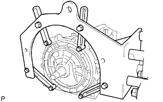
FIX AUTOMATIC TRANSMISSION CASE SUB-ASSEMBLY
-
Install the transmission case on the overhaul attachment.
-
-
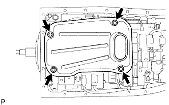
REMOVE AUTOMATIC TRANSMISSION OIL PAN SUB-ASSEMBLY
Note
Do not turn the transmission over as this will contaminate the valve body with foreign matter on the bottom of the pan.
-
Remove the drain plug and the 20 bolts.
-
-
INSPECT AUTOMATIC TRANSMISSION OIL PAN SUB-ASSEMBLY
-
Remove the magnets, and use them to collect steel particles.
-
Carefully look at the foreign matter and particles in the pan and on the magnets to anticipate the type of wear you will find in the transmission.
-
Steel (magnetic): bearing, gear and clutch plate wear
-
Brass (non-magnetic): bushing wear
-
-
-
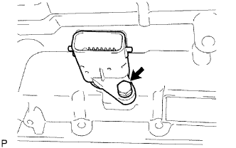
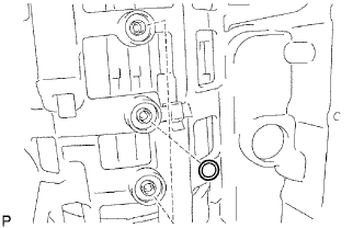
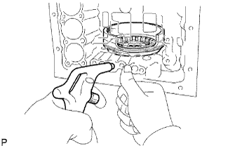
REMOVE VALVE BODY OIL STRAINER ASSEMBLY
-
Turn over the transmission.
-
Remove the 4 bolts holding the valve body oil strainer assembly to the valve body.
-
Remove the O-ring form the valve body oil strainer assembly.
-
-
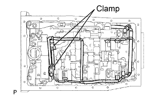
REMOVE TRANSMISSION WIRE
-
Remove the ATF temperature sensor.
-
Remove the bolt and clamp.
-
Disconnect the 7 connectors from the shift solenoid valves.
-
Remove the bolt from the case.
-
Pull the transmission wire out of the transmission case.
-
Remove the O-ring from the transmission wire.
-
-
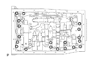
REMOVE TRANSMISSION VALVE BODY ASSEMBLY
-
Remove the 19 bolts.
-
Remove the valve body assembly.
-
-
REMOVE TRANSAXLE CASE GASKET
-
Remove the 3 transaxle case gaskets.
-
-
REMOVE BRAKE DRUM GASKET
-
Remove the 3 brake drum gaskets.
-
-
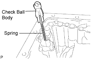
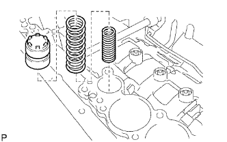
REMOVE CHECK BALL BODY
-
Remove the check ball body and spring.
-
-
REMOVE C-2 ACCUMULATOR PISTON
-
Applying compressed air to the oil hole, and remove the C-2 accumulator piston and spring.
-
Remove the 2 O-rings from the piston.
Note
Be careful as the C-3 and B-3 accumulator piston may jump out.
-
-
REMOVE B-3 ACCUMULATOR PISTON
-
Applying compressed air to the oil hole, and remove the C-2 accumulator piston and spring.
-
Remove the 2 O-rings from the piston.
Note
Be careful as the C-3 accumulator piston may jump out.
-
-
REMOVE C-3 ACCUMULATOR PISTON
-
Applying compressed air to the oil hole, and remove the B3 accumulator piston and spring.
-
Remove the 2 O-rings from the piston.
-
-
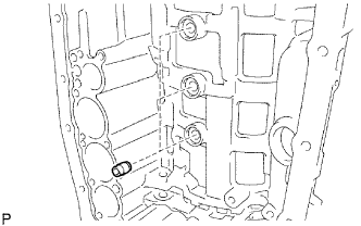
REMOVE C-1 ACCUMULATOR VALVE
-
Remove the C-1 accumulator valve and 2 springs.
-
-
REMOVE PARKING LOCK PAWL BRACKET
-
Remove the 3 bolts and parking lock pawl bracket.
-
-
REMOVE PARKING LOCK ROD SUB-ASSEMBLY
-
Disconnect the parking lock rod from the manual valve lever.
-
-
REMOVE PARKING LOCK PAWL SHAFT
-
Pull out the parking lock pawl shaft from the front side, and then remove the lock pawl and spring.
-
Remove the E-ring from the shaft.
-
-
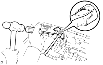
REMOVE MANUAL VALVE LEVER SUB-ASSEMBLY
-
Using a hammer and screwdriver, cut off the spacer and remove it from the shaft.
-
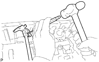
Using a pin punch and hammer, tap out the spring pin.
Tech Tips
Slowly drive out the spring pin so that it does not fall into the transmission case.
-
Pull the manual valve lever shaft out through the case, and remove the manual valve lever.
-
-
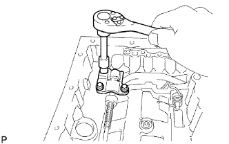
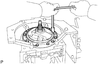
REMOVE MANUAL VALVE LEVER SHAFT OIL SEAL
-
Using a screwdriver, pry out the 2 oil seals.
-
-
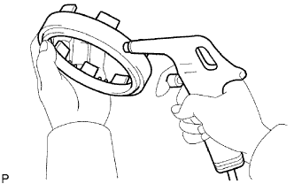
REMOVE OIL PUMP ASSEMBLY
-
Remove the 10 bolts holding the oil pump from the transmission case.
-
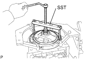
Using SST, remove the oil pump.
- SST
- 09350-30020 ( 09350-07020 )
-
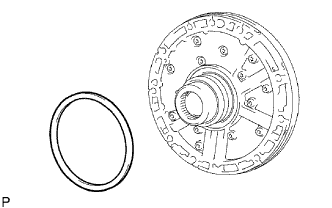
Remove the No. 1 thrust bearing race from the front oil pump.
-
-
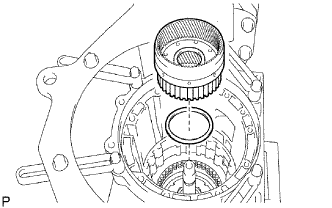
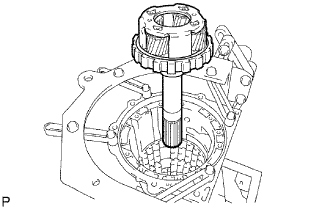
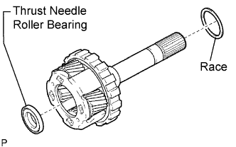
REMOVE CLUTCH DRUM AND INPUT SHAFT ASSEMBLY
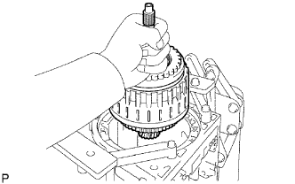
-
Remove the clutch drum and input shaft drum assembly from the transmission case.
-
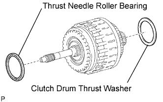
Remove the clutch drum thrust washer and thrust needle roller bearing.
-
-
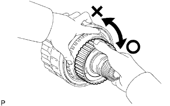
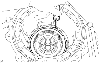
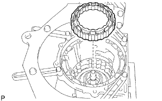
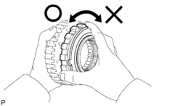
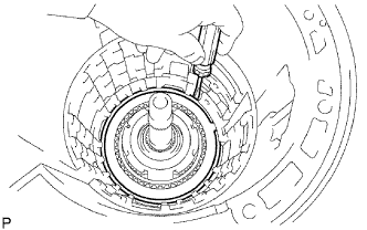
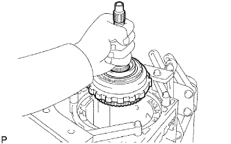
INSPECT NO. 2 1-WAY CLUTCH ASSEMBLY
-
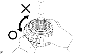
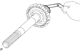
Hold the reverse clutch hub and turn the No. 2 1-Way clutch assembly.
-
Check that the No. 2 1-Way clutch assembly turns freely clockwise and locks when turned counterclockwise.
-
-
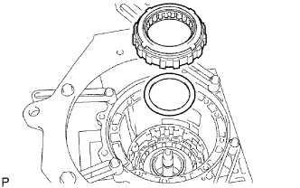
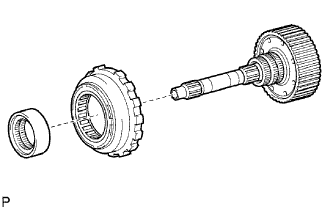
REMOVE NO. 2 1-WAY CLUTCH ASSEMBLY
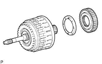
-
Remove the No. 2 1-way clutch assembly and No. 2 clutch drum thrust washer from the clutch drum and input shaft assembly.
-
-
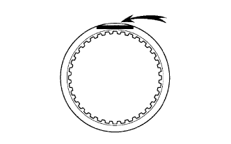
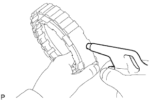
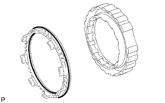
REMOVE NO. 3 BRAKE SNAP RING
-
Using a screwdriver, remove the No. 3 brake snap ring from the case.
-
-
REMOVE NO. 3 BRAKE DISC
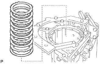
-
Remove the flange, cushion plate, 4 discs and 4 plates from the case.
-
-
INSPECT NO. 3 BRAKE DISC
-
Replace all discs if one of the following problems is present: 1) a disc, plate or flange is worn or burnt, 2) the lining of a disc is peeled off or discolored, or 3) grooves or printed numbers have even a little bit of damage.
Note
Before assembling new discs, soak them in ATF for at least 15 minutes.
-
-
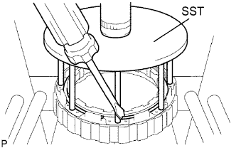
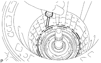
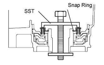
REMOVE 2ND BRAKE PISTON HOLE SNAP RING
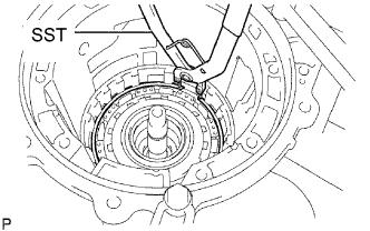
-
Using SST, remove the snap ring.
- SST
- 09350-30020 ( 09350-07060 )
-
-
REMOVE 1-WAY CLUTCH ASSEMBLY
-
Remove the 1-way clutch assembly and No. 1 planetary carrier thrust washer from the case.
-
-
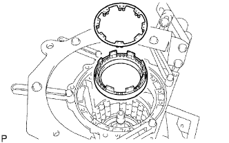
REMOVE 2ND BRAKE CYLINDER
-
Remove the 2nd brake cylinder from the case.
-
-
REMOVE 2ND BRAKE PISTON
-
Using SST, a press and screwdriver, remove the snap ring.
- SST
- 09351-40010
-
Hold the 2nd brake piston and apply compressed air (392 kPa, 4.0 kgf/cm2, 57 psi) to the brake cylinder to remove the 2nd brake piston.
-
Remove the 2 O-rings from the 2nd brake piston.
-
-
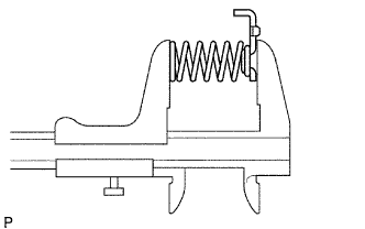
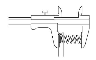
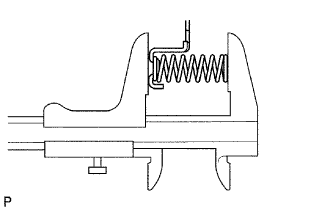
INSPECT NO. 3 BRAKE PISTON RETURN SPRING SUB-ASSEMBLY
-
Using a vernier caliper, measure the free length of the spring together with the spring seat.
Standard free length 15.72 mm (0.619 in.)
-
-
REMOVE FRONT PLANETARY GEAR ASSEMBLY
-
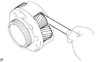
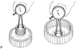
INSPECT FRONT PLANETARY GEAR ASSEMBLY
-
Using a feeler gauge, measure the front planetary pinion gear thrust clearance.
Standard clearance 0.2 to 0.60 mm (0.008 to 0.024 in.) Maximum clearance 0.65 mm (0.026 in.)
-
If the clearance is greater than the maximum, replace the front planetary gear assembly.
-
-
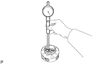
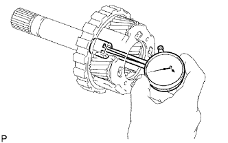
Using a dial indicator, measure the inside diameter of the front planetary gear bushing.
Maximum inside diameter 57.48 mm (2.263 in.)
-
If the inside diameter is greater than the maximum, replace the front planetary gear.
-
-
-
INSPECT 1-WAY CLUTCH ASSEMBLY
-
Install the 1-way clutch assembly to the 1-way clutch inner race.
-
Hold the 1-way clutch inner race and turn the 1-way clutch assembly.
-
Check that the 1-way clutch assembly turns freely counterclockwise and locks when turned clockwise.
-
Remove the 1-way clutch assembly from 1-way clutch inner race.
-
-
REMOVE FRONT PLANETARY RING GEAR
-
Remove the front planetary ring gear and bearing from the transmission case.
-
-
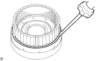
REMOVE CENTER PLANETARY RING GEAR
-
Using a screwdriver, remove the snap ring.
-
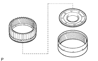
Remove the center planetary ring gear and front planetary ring gear flange from the front planetary ring gear.
-
-
REMOVE NO. 1 BRAKE DISC
-
Remove the flange, 3 discs and 3 plates from the case.
-
-
INSPECT NO. 1 BRAKE DISC
-
Replace all discs if one of the following problems is present: 1) a disc, plate or flange is worn or burnt, 2) the lining of a disc is peeled off or discolored, or 3) grooves or printed numbers have even a little bit of damage.
Note
Before assembling new discs, soak them in ATF for at least 15 minutes.
-
-
REMOVE BRAKE PISTON RETURN SPRING SNAP RING
-
Using a screwdriver, remove the brake piston return spring snap ring from the case.
-
-
REMOVE BRAKE PISTON RETURN SPRING SUB-ASSEMBLY
-
Remove the brake piston return spring and No. 1 brake piston with the No. 1 brake cylinder from the transmission case.
-
-
INSPECT BRAKE PISTON RETURN SPRING SUB-ASSEMBLY
-
Using a vernier caliper, measure the free length of the spring together with the spring seat.
Standard free length 17.05 mm (0.671 in.)
-
-
REMOVE NO. 1 BRAKE PISTON
-
Hold the No. 1 brake piston and apply compressed air (392 kPa, 4 kgf/cm2, 57 psi) to the transmission case to remove the No. 1 brake piston.
Tech Tips
If the piston does not pop out with compressed air, lift the piston out with needle-nose pliers.
-
Remove the 2 O-rings from the No. 1 brake piston.
-
-
REMOVE NO. 2 BRAKE DISC
-
Using a screwdriver, remove the snap ring from the case.
-
Remove the flange, brake piston return spring, 3 discs and 3 plates from the case.
-
-
INSPECT NO. 2 BRAKE DISC
-
Replace all discs if one of the following problems is present: 1) a disc, plate or flange is worn or burnt, 2) the lining of a disc is peeled off or discolored, or 3) grooves or printed numbers have even a little bit of damage.
Note
Before assembling new discs, soak them in ATF for at least 15 minutes.
-
-
INSPECT NO. 2 BRAKE PISTON RETURN SPRING SUB-ASSEMBLY
-
Using a vernier caliper, measure the free length of the spring together with the spring seat.
Standard free length 17.45 mm (0.687 in.)
-
-
REMOVE NO. 2 BRAKE PISTON
-
Hold the No. 2 brake piston and apply compressed air (392 kPa, 4 kgf/cm2, 57 psi) to the transmission case to remove the No. 2 brake piston.
Tech Tips
If the piston does not pop out with compressed air, lift the piston out with needle-nose pliers.
-
Remove the 2 O-rings from the No. 2 brake piston.
-
-
REMOVE CENTER PLANETARY GEAR ASSEMBLY
-
Remove the center planetary gear assembly, planetary sun gear and No. 4 thrust bearing race from the case.
-
-
INSPECT CENTER PLANETARY GEAR ASSEMBLY
-
Using a feeler gauge, measure the center planetary gear pinion thrust clearance.
Standard clearance 0.12 to 0.68 mm (0.005 to 0.027 in.) Maximum clearance 0.73 mm (0.029 in.)
-
If the clearance is greater than the maximum, replace the center planetary gear assembly.
-
-
-
REMOVE INTERMEDIATE SHAFT
-
Using a screwdriver, remove the snap ring from the case.
-
Remove the intermediate shaft with the No. 3 1-way clutch assembly from the case.
-
-
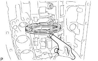
INSPECT NO. 3 1-WAY CLUTCH ASSEMBLY
-
Hold the rear planetary ring gear flange sub assembly and turn the 1-way clutch assembly.
-
Check that the 1-way clutch assembly turns freely counterclockwise and locks when turned clockwise.
-
-
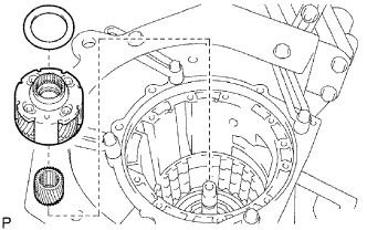
REMOVE NO. 3 1-WAY CLUTCH ASSEMBLY
-
Remove the No. 3 1-way clutch assembly and 1-way clutch inner race from the intermediate shaft.
-
-
REMOVE REAR PLANETARY RING GEAR FLANGE SUB-ASSEMBLY
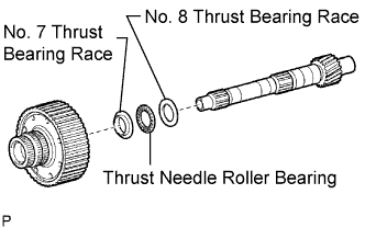
-
Remove the No. 8 thrust bearing race, thrust needle roller bearing, No. 7 thrust bearing race and planetary ring gear flange from the intermediate shaft.
-
-
INSPECT REAR PLANETARY RING GEAR FLANGE SUB-ASSEMBLY
-
Using a caliper gauge, measure the inside diameter of the rear planetary ring gear bushing.
Maximum inside diameter 32.175 mm (1.267 in.)
-
If the inside diameter is greater than the maximum, replace the rear planetary ring gear.
-
-
-
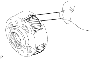
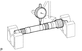
INSPECT INTERMEDIATE SHAFT
-
Using a dial indicator, check the intermediate shaft runout.
Maximum runout 0.08 mm (0.003 in.) Note
If the bend exceeds the specification, replace the intermediate shaft with a new one.
-
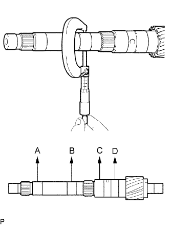
Using a micrometer, check the outer diameter of the intermediate shaft positions shown in the diagram.
Standard diameter A 25.962 to 25.975 mm (1.022 to 1.023 in.) B 25.962 to 25.975 mm (1.022 to 1.023 in.) C 32.062 to 32.075 mm (1.262 to 1.263 in.) D 32.062 to 32.075 mm (1.262 to 1.263 in.) Minimum diameter A 25.912 mm (1.020 in.) B 25.912 mm (1.020 in.) C 32.012 mm (1.260 in.) D 32.012 mm (1.260 in.) Note
If the outer diameter is outside the standard or less than the minimum, replace the intermediate shaft with the new one.
-
-
REMOVE BRAKE PLATE STOPPER SPRING
-
Remove the brake plate stopper spring from the case.
-
-
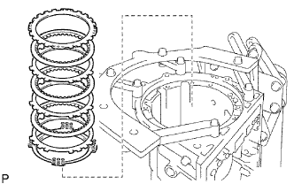
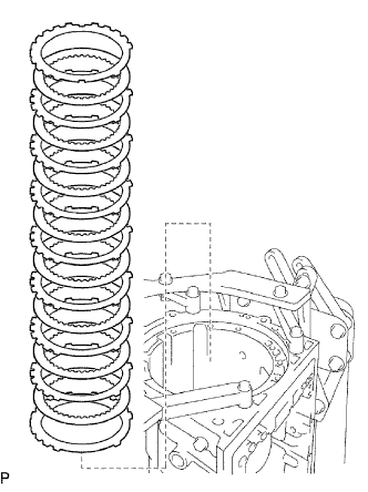
REMOVE NO. 4 BRAKE DISC
-
Remove the 7 plates, 8 discs and 2 flanges from the case.
-
-
INSPECT NO. 4 BRAKE DISC
-
Replace all discs if one of the following problems is present: 1) a disc, plate or flange is worn or burnt, 2) the lining of a disc is peeled off or discolored, or 3) grooves or printed numbers have even a little bit of damage.
Note
Before assembling new discs, soak them in ATF for at least 15 minutes.
-
-
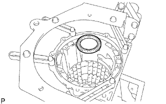
REMOVE REAR PLANETARY GEAR ASSEMBLY
-
Remove the rear planetary gear assembly from the case.
-
Remove the No. 9 thrust bearing race and thrust needle roller bearing from the rear planetary gear assembly.
-
Remove the thrust needle roller bearing from the case.
-
-
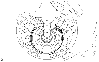
INSPECT REAR PLANETARY GEAR ASSEMBLY
-
Using a feeler gauge, measure the rear planetary gear pinion thrust clearance.
Standard clearance 0.2 to 0.6 mm (0.008 to 0.024 in.) Maximum clearance 0.65 mm (0.026 in.)
-
If the clearance is greater than the maximum, replace the planetary gear assembly.
-
-
Using a caliper gauge, measure the inside diameter of the rear planetary gear bushing.
Maximum inside diameter 20.075 mm (0.790 in.)
-
If the inside diameter is greater than the maximum, replace the rear planetary gear assembly.
-
-
-
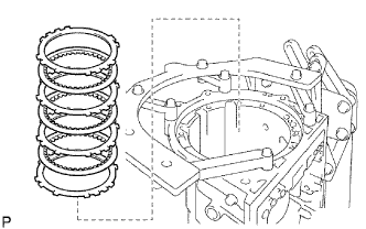
REMOVE 1ST AND REVERSE BRAKE RETURN SPRING SUB-ASSEMBLY
-
Place SST on the spring retainer and compress the brake return spring.
- SST
- 09350-30020 ( 09350-07050 )
-
Using SST, remove the snap ring and brake return spring.
- SST
- 09350-30020 ( 09350-07070 )
-
-
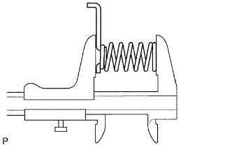
INSPECT 1ST AND REVERSE BRAKE RETURN SPRING SUB-ASSEMBLY
-
Using a vernier caliper, measure the free length of the spring together with the spring seat.
Standard free length 23.74 mm (0.935 in.)
-
-
REMOVE 1ST AND REVERSE BRAKE PISTON
-
Hold the No. 2 brake piston and apply compressed air (392 kPa, 4 kgf/cm2, 57 psi) to the transmission case to remove the No. 2 brake piston.
Tech Tips
If the piston does not pop out with compressed air, lift the piston out with needle-nose pliers.
-
Remove the O-ring from the No. 2 brake piston.
-
-
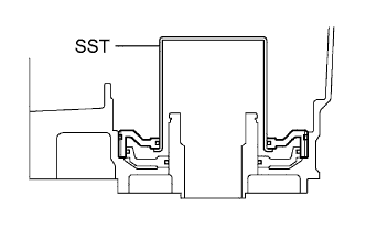
REMOVE BRAKE REACTION SLEEVE
-
Using SST, remove the reaction sleeve.
- SST
- 09350-30020 ( 09350-07080 )
-
Remove the O-ring from the reaction sleeve.
-
-
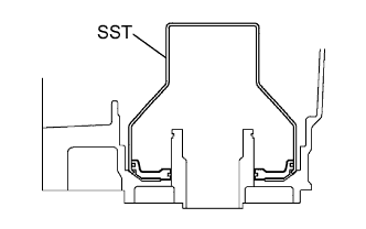
REMOVE NO. 4 BRAKE PISTON
-
Using SST, remove the No. 4 brake piston.
- SST
- 09350-30020 ( 09350-07090 )
-
Remove the 2 O-rings from the No. 4 piston.
-