CLUTCH UNIT REMOVAL

-
REMOVE MANUAL TRANSMISSION UNIT ASSEMBLY
for R150 manual transmission: Click here
for R150F/R151F manual transmission: Click here
-
REMOVE CLUTCH RELEASE BEARING ASSEMBLY
-
Remove the clutch release bearing assembly together with the clutch release fork sub-assembly from the clutch housing.
-
Remove the clutch release fork sub-assembly from the clutch release bearing assembly.
-
Remove the release bearing hub clip from the clutch release bearing assembly.
-
-
REMOVE RELEASE FORK SUPPORT
-
Remove the release fork support from the manual transmission unit.
-
-
REMOVE CLUTCH COVER ASSEMBLY
-
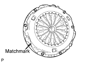
Place matchmarks on the clutch cover and flywheel.
-
Loosen each set bolt one turn at a time until spring tension is released.
-
Remove the 6 set bolts and pull off the clutch cover.
Note
Do not drop the clutch disc.
-
-
REMOVE CLUTCH DISC ASSEMBLY
Note
Keep the lining part of the clutch disc, pressure plate and surface of the flywheel away from oil and foreign matter.
-
INSPECT INPUT SHAFT FRONT BEARING
-
Turn the bearing by hand by applying rotational force.
If the bearing sticks or has much resistance, replace the input shaft bearing.
Tech Tips
The bearing is permanently lubricated and requires no cleaning or lubrication.
-
-
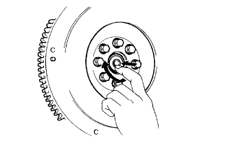
REMOVE INPUT SHAFT FRONT BEARING
-
Remove any 2 diametrically opposite bolts.
-
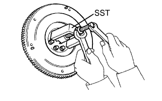
Using SST, remove the input shaft bearing.
- SST
- 09303-35011
-
-
INSPECT CLUTCH DISC ASSEMBLY
Note
When replacing the clutch disc assembly, make sure to perform an inspection of the flywheel sub-assembly and clutch cover assembly.
-
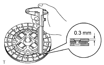
Using a vernier caliper, measure the rivet head depth.
Minimum rivet depth 0.3 mm (0.0118 in.) If the depth is less than the minimum, replace the clutch disc assembly.
-
Install the clutch disc to the transmission unit.
Note
Be careful not to insert the clutch disc facing the wrong direction.
-
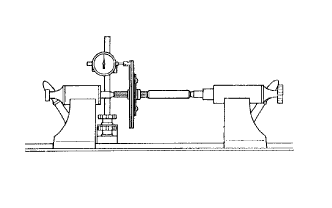
Using a dial indicator, check the disc runout.
Maximum runout 0.8 mm (0.0314 in.) If the runout is greater than the maximum, replace the clutch disc assembly.
-
-
INSPECT CLUTCH COVER ASSEMBLY
-
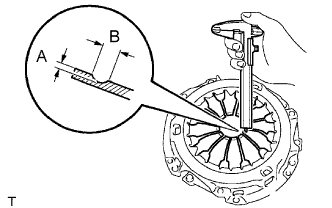
Using a vernier caliper, measure the depth and width of the worn areas of the diaphragm spring.
Maximum wear Measurement Maximum wear A (Depth) 0.5 mm (0.0196 in.) B (Width) 6.0 mm (0.236 in.) If the depth or width is greater than the maximum, replace the clutch cover assembly.
-
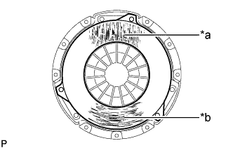
Text in Illustration *1 Hair cracks, scratches or discoloration *2 Hair cracks, discoloration or excessive wear Perform a visual inspection of the clutch cover assembly.
-
Inspect for hair cracks or scratches extending from the center outwards, or discoloration.
-
Inspect for hair cracks in a circular pattern, discoloration or excessive wear.
If there is any damage, replace the clutch cover assembly.
-
-
-
INSPECT FLYWHEEL SUB-ASSEMBLY
-
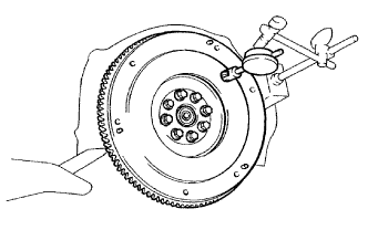
Using a dial indicator, measure the flywheel runout.
Maximum runout 0.1 mm (0.00393 in.) If the runout is greater than the maximum, replace the flywheel sub-assembly.
-
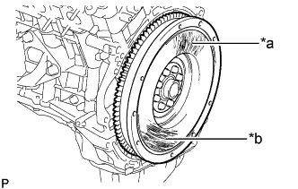
Text in Illustration *1 Hair cracks, scratches or discoloration *2 Hair cracks, discoloration or excessive wear Perform a visual inspection of the flywheel sub-assembly.
-
Inspect for hair cracks or scratches extending from the center outwards, or discoloration.
-
Inspect for hair cracks in a circular pattern, discoloration or excessive wear.
If there is any damage, replace the flywheel sub-assembly.
-
-
-
INSPECT CLUTCH RELEASE BEARING ASSEMBLY
-
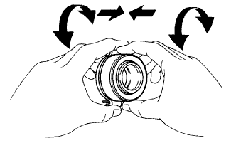
Turn the bearing by hand while applying force in the axial direction.
If the bearing sticks or has much resistance, replace the release bearing.
Tech Tips
The bearing is permanently lubricated and requires no cleaning or lubrication.
-