AUTOMATIC TRANSMISSION SYSTEM DIAGNOSIS SYSTEM

-
DESCRIPTION

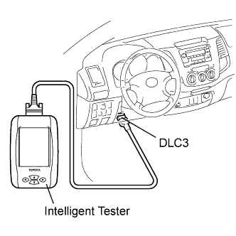
When troubleshooting Multiplex OBD (M-OBD) vehicles, the vehicle must be connected to the intelligent tester. Various data output from the vehicle's ECM can then be read.
The Malfunction Indicator Lamp (MIL) illuminates when the vehicle's on-board computer detects a malfunction in the computer itself or in drive system components. In addition, the applicable Diagnostic Trouble Codes (DTCs) are recorded in the ECM memory Click here.
When the malfunction does not reoccur, the MIL stays illuminated until the ignition switch is turned OFF, and the MIL turns OFF when the engine is started. However, the DTCs remain recorded in the ECM memory.
To check DTCs, connect the tester to the Data Link Connector 3 (DLC3) on the vehicle or connect terminals TC and CG on the DLC3 (DTCs will be displayed on the combination meter).
-
NORMAL MODE AND CHECK MODE
The diagnosis system operates in "normal mode" during normal vehicle use. In normal mode, "2 trip detection logic" is used to ensure accurate detection of malfunctions. "Check mode" is also available to technicians as an option. In check mode, "1 trip detection logic" is used for simulating malfunction symptoms and increasing the system's ability to detect malfunctions, including intermittent malfunctions Click here.
-
2 TRIP DETECTION LOGIC
When a malfunction is first detected, the malfunction is temporarily stored in the ECM memory (1st trip). If the same malfunction is detected during the next subsequent drive cycle, the MIL is illuminated (2nd trip).
-
FREEZE FRAME DATA
Freeze frame data records the engine conditions (fuel system, calculated engine load, engine coolant temperature, fuel trim, engine speed, vehicle speed, etc.) when a malfunction is detected. When troubleshooting, freeze frame data can help determine if the vehicle was running or stopped, if the engine was warmed up or not, if the air-fuel ratio was lean or rich, and other data from the time the malfunction occurred.
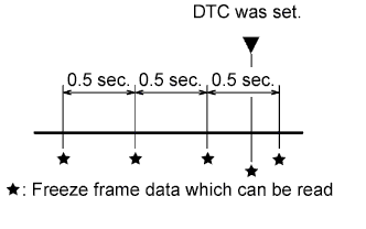
The tester records freeze frame data in five different instances: 1) 3 times before the DTC is set, 2) once when the DTC is set, and 3) once after the DTC is set. These data can be used to simulate the vehicle's condition around the time when the malfunction occurred. The data may help find the cause of the malfunction, or help in judging if the DTC is being caused by a temporary malfunction or not.
-
CHECK DLC3
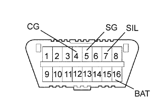
The vehicle's ECM uses ISO 14230 (M-OBD) communication protocol. The terminal arrangement of the DLC3 complies with ISO 15031-03 and matches the ISO 14230 format.
Symbols (Terminal No.) Terminal Description Condition Specified Condition SIL (7) - SG (5) Bus "+" line During transmission Pulse generation CG (4) - Body ground Chassis ground Always Below 1 Ω SG (5) - Body ground Signal ground Always Below 1 Ω BAT (16) - Body ground Battery positive Always 9 to 14 V If the result is not as specified, the DLC3 may have a malfunction. Repair or replace the harness and connector.
Tech Tips
Connect the cable of the tester to the DLC3, turn the ignition switch ON and attempt to use the tester. If the display indicates that a communication error has occurred, there is a problem either with the vehicle or with the tester.
-
If communication is normal when the tester is connected to another vehicle, inspect the DLC3 on the original vehicle.
-
If communication is still not possible when the tester is connected to another vehicle, the problem is probably in the tester itself. Consult the Service Department listed in the tester's instruction manual.
-
-
CHECK MIL

-
The MIL illuminates when the ignition switch is turned ON and the engine is not running.
Tech Tips
If the MIL is not illuminated, check the MIL circuit Click here.
-
When the engine is started, check that the MIL turns OFF.
If the lamp remains illuminated, the diagnosis system has detected a malfunction or abnormality in the system.
-