AUTOMATIC TRANSMISSION ASSEMBLY INSTALLATION

-
INSPECT TORQUE CONVERTER CLUTCH ASSEMBLY
-
Inspect the torque converter clutch assembly Click here.
-
-
INSTALL TORQUE CONVERTER CLUTCH ASSEMBLY
-
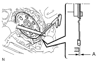
Install the torque converter clutch to the automatic transmission.
-
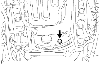
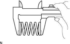
Using a vernier caliper and straightedge, measure dimension A between the transmission and the end surface of the drive plate.
Standard dimension A = 22.28 mm (0.8772 in.) -
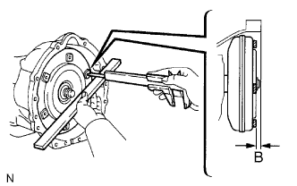
Using a vernier caliper and straightedge, measure dimension B shown in the illustration. Check that B is greater than A.
Standard dimension B = A + 1.00 mm (0.0394 in.) or more
-
-
INSTALL TRANSFER ASSEMBLY
-
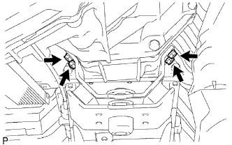
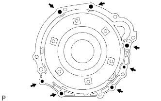
Install the transfer to the transmission.
-
Install the 2 clamps and 8 bolts.
- Torque:
- 24 N*m { 244 kgf*cm, 17 ft.*lbf }
-
-
INSTALL NO. 1 ENGINE MOUNTING INSULATOR REAR
-
Install the engine mounting insulator to the transmission with the 4 bolts.
- Torque:
- 65 N*m { 663 kgf*cm, 48 ft.*lbf }
-
-
INSTALL AUTOMATIC TRANSMISSION ASSEMBLY
-
Install the transmission to the engine with the 7 bolts.
- Torque:
- 71 N*m { 724 kgf*cm, 52 ft.*lbf, for 17mm head }
- 37 N*m { 377 kgf*cm, 27 ft.*lbf, for 14 mm head }
-
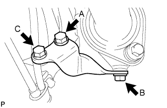
Install the exhaust manifold stay with the 3 bolts.
- Torque:
- 44 N*m { 449 kgf*cm, 32 ft.*lbf, for bolt A }
- 30 N*m { 306 kgf*cm, 22 ft.*lbf, for bolt B }
- 71 N*m { 724 kgf*cm, 52 ft.*lbf, for bolt C }
-
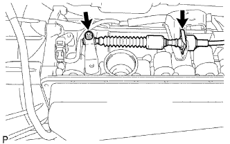
Hold the crankshaft pulley bolt with a wrench and install the 6 torque converter clutch mounting bolts.
- Torque:
- 41 N*m { 418 kgf*cm, 30 ft.*lbf }
-
-
INSTALL FLYWHEEL HOUSING DUST SEAL
-
CONNECT WIRE HARNESS
-
CONNECT CONNECTOR
-
Transmission side:
Connect the connectors.
-
Connect the temperature sensor connector.
-
Connect the park/neutral position switch connector.
-
Connect the 2 speed sensor connectors.
-
Connect the transmission wire connector.
-
-
Transfer side:
Connect the connectors.
-
Connect the indicator switch connector (for 4WD).
-
Connect the speedometer sensor connector.
-
Connect the indicator switch connector (for L4).
-
Connect the indicator switch connector (neutral).
-
-
-
INSTALL NO. 3 FRAME CROSSMEMBER SUB-ASSEMBLY
-
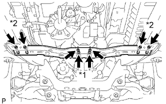
*1: Install the 4 set bolts of the engine mounting insulator.
- Torque:
- 27 N*m { 275 kgf*cm, 20 ft.*lbf }
-
*2: Install the frame crossmember with the 4 bolts and 4 nuts.
- Torque:
- 50 N*m { 510 kgf*cm, 37 ft.*lbf }
-
-
INSTALL STARTER ASSEMBLY
-
Install the starter assembly Click here.
-
-
INSTALL TRANSMISSION CONTROL CABLE BRACKET
-
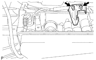
Install the control cable bracket with the 2 bolts.
- Torque:
- 28 N*m { 286 kgf*cm, 21 ft.*lbf }
-
-
CONNECT TRANSMISSION CONTROL SHIFT CABLE ASSEMBLY
-
Connect the control cable with the clip.
-
Connect the control cable with the nut.
- Torque:
- 14 N*m { 143 kgf*cm, 10 ft.*lbf }
-
-
INSTALL OIL COOLER TUBE
-
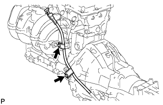
Loosely install the tip of the oil cooler tube inlet to the automatic transmission by hand.
-
Loosely install the tip of the oil cooler tube outlet to the automatic transmission by hand.
-
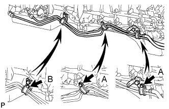
Install the 3 clamps with the 3 bolts.
- Torque:
- 5.0 N*m { 50 kgf*cm, 44 in.*lbf, for A }
- 12 N*m { 122 kgf*cm, 9 ft.*lbf, for B }
-
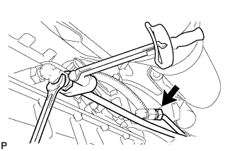
Using a union nut wrench, tighten the inlet and outlet tubes.
- Torque:
- 34 N*m { 346 kgf*cm, 25 ft.*lbf }
Note
Use the formula to calculate special torque values for situations where a union nut wrench is combined with a torque wrench Click here.
-
-
INSTALL TRANSMISSION OIL FILLER TUBE SUB-ASSEMBLY
-
Coat a new O-ring with ATF, and install it to the oil filler tube.
-
Install the oil filler tube with the 2 bolts.
- Torque:
- 12 N*m { 122 kgf*cm, 9 ft.*lbf }
-
Install the oil dipstick.
-
-
INSTALL REAR PROPELLER SHAFT ASSEMBLY
-
Install the rear propeller shaft assembly Click here.
-
-
INSTALL FRONT PROPELLER SHAFT ASSEMBLY
-
Install the front propeller shaft assembly Click here.
-
-
INSTALL TRANSFER CASE LOWER PROTECTOR
-
Install the transfer case lower protector with the 4 bolts.
- Torque:
- 18 N*m { 184 kgf*cm, 13 ft.*lbf }
-
-
INSTALL FRONT EXHAUST PIPE ASSEMBLY
-
Using a vernier caliper, measure the free length of the compression spring.
Minimum length 40 mm (1.57 in.) If the length is less than the minimum, replace the compression spring.
-
Install the front pipe to the pipe support.
-
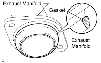
Install a new gasket to the outlet pipe.
Tech Tips
Using a plastic-faced hammer, uniformly strike the gasket so that the gasket and exhaust pipe are properly fit.
Note
-
Be careful with the installation direction of the gasket.
-
Do not reuse the gasket.
-
To ensure a proper seal, do not use the front pipe to force the gasket onto the outlet pipe.
-
-
Install the front pipe with the 2 compression springs and 2 bolts. Alternately tighten the bolts in several passes.
- Torque:
- 43 N*m { 438 kgf*cm, 32 ft.*lbf }
-
-
INSTALL TRANSFER HIGH AND LOW SHIFT LEVER ASSEMBLY
-
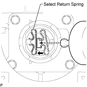
While pushing the select return spring to the left with the end of the transfer high and low shift lever, insert the end of the shift lever into the shift fork.
-
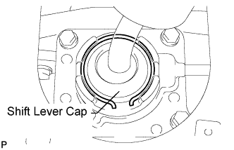
While holding down the shift lever cap, install the snap ring to install the transfer high and low shift lever.
-
Return the transfer front drive shift boot to its original position.
-
-
INSTALL SHIFT LEVER BOOT ASSEMBLY
-
Install the shift lever boot with the 4 screws.
-
-
ADJUST SHIFT LEVER POSITION
-
Remove the nut and disconnect the control cable.
-
Remove the clip and disconnect the control cable from the control cable bracket.
-
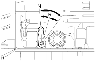
Push the control shaft rearward as much as possible.
-
Return the control shaft lever 2 notches to the N position.
-
While holding the control shaft lever slightly toward the R position side, tighten the nut.
- Torque:
- 14 N*m { 143 kgf*cm, 10 ft.*lbf }
-
-
ADD TRANSFER OIL
-
Remove the case plug (for filler) and gasket.
-
Pour oil so that the oil level is between 0 to 5.0 mm (0 to 0.197 in.) from the bottom lip of the case plug (for filler) hole.
Note
-
When adding oil, pour it slowly.
-
Add oil a little at a time, waiting several minutes between each addition of oil.
-
-
Wait approximately 5 minutes and check that the oil level has not changed.
-
Install a new gasket and the case plug (for filler).
- Torque:
- 37 N*m { 377 kgf*cm, 27 ft.*lbf }
-
-
ADD AUTOMATIC TRANSMISSION FLUID
-
Add automatic transmission fluid Click here.
Fluid type Toyota Genuine ATF TYPE T-IV
-
-
CONNECT CABLE TO NEGATIVE BATTERY TERMINAL
-
PERFORM INITIALIZATION
-
Perform initialization Click here.
Note
Certain systems need to be initialized after disconnecting and reconnecting the cable from the negative (-) battery terminal.
-
-
INSPECT SHIFT LEVER POSITION
-
When moving the shift lever from P to R with the ignition switch ON and the brake pedal depressed, make sure that the shift lever moves smoothly and correctly into position.
-
Start the engine and make sure that the vehicle moves forward after moving the shift lever from N to D, and moves rearward after shifting to R.
If the results are not as specified, inspect the park/neutral position switch and adjust the shift lever position.
-
-
INSTALL CONSOLE BOX ASSEMBLY
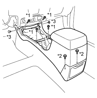
Text in Illustration *1 Screw *2 Bolt *3 Clip
-
Install the console box with the 4 screws and 2 bolts.
-
Install the 2 clips.
-
-
INSTALL UPPER CONSOLE PANEL SUB-ASSEMBLY
-
Attach the 12 claws to install the upper console panel.

Text in Illustration *A for 2WD *B for 4WD
-
-
INSTALL PARKING BRAKE HOLE COVER SUB-ASSEMBLY
-
Attach the 4 claws to install the parking brake hole cover.
-
-
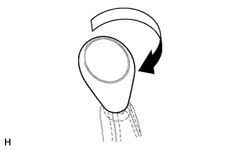
INSTALL SHIFT LEVER KNOB SUB-ASSEMBLY
-
Install the shift lever knob and twist it in the direction indicated by the arrow.
-
-
CHECK FOR EXHAUST GAS LEAKS
-
INSPECT AUTOMATIC TRANSMISSION FLUID
-
Inspect the automatic transmission fluid Click here.
-
-
INSTALL NO. 2 ENGINE UNDER COVER
- Torque:
- 28 N*m { 286 kgf*cm, 21 ft.*lbf }
-
INSTALL NO. 1 ENGINE UNDER COVER
- Torque:
- 28 N*m { 286 kgf*cm, 21 ft.*lbf }