VALVE BODY ASSEMBLY INSTALLATION

Note
When working with FIPG material, perform the following:
-
Using a razor blade and gasket scraper, remove all old FIPG material from the gasket surfaces.
-
Clean all components thoroughly to remove all foreign matter.
-
Clean both sealing surfaces with a non-residue solvent.
-
Apply FIPG material in a continuous line approximately 1 mm (0.04 in.) in diameter on the sealing surface.
-
Reassemble parts within 10 minutes of applying FIPG material. Failing to do so will require the FIPG material to be removed and reapplied.
-
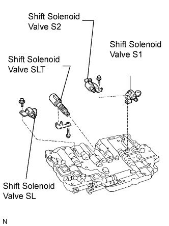
INSTALL TRANSMISSION VALVE BODY ASSEMBLY
-
Install the shift solenoid valve SL with the bolt.
- Torque:
- 10 N*m { 102 kgf*cm, 7 ft.*lbf }
-
Install the shift solenoid valve S1 and S2 with the bolt.
- Torque:
- 6.6 N*m { 67 kgf*cm, 58 in.*lbf }
-
Install the shift solenoid valve SLT with the plate and bolt.
- Torque:
- 6.4 N*m { 65 kgf*cm, 57 in.*lbf }
-
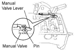
Align the groove of the manual valve with the pin of the lever.
-
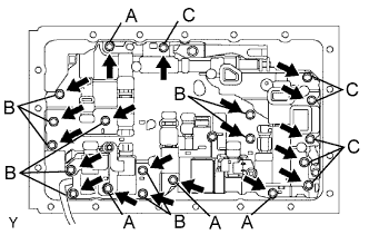
Install the 20 bolts.
- Torque:
- 11 N*m { 110 kgf*cm, 8 ft.*lbf }
Tech Tips
Each bolt length is indicated below.
Bolt length 23 mm (0.91 in.) for A 28 mm (1.10 in.) for B 36 mm (1.42 in.) for C
-
-
INSTALL TRANSMISSION WIRE
-
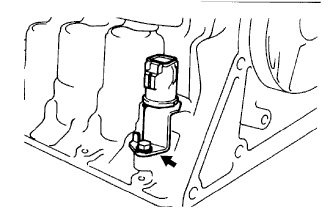
Coat a new O-ring with ATF and install it to the transmission wire.
-
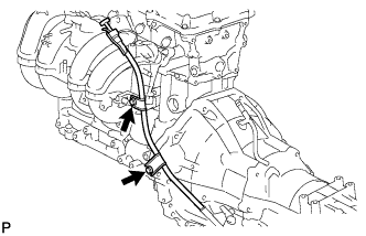
Install the transmission wire to the case, and install the stopper plate with the bolt.
- Torque:
- 5.4 N*m { 55 kgf*cm, 48 in.*lbf }
-
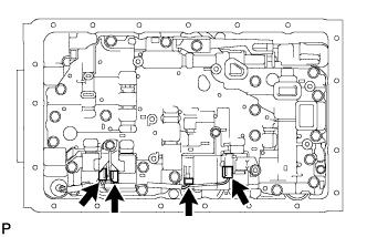
Connect the 4 connectors to the 4 shift solenoid valves.
-
-
INSTALL VALVE BODY OIL STRAINER ASSEMBLY
-
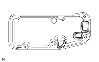
Install 3 new gaskets.
-
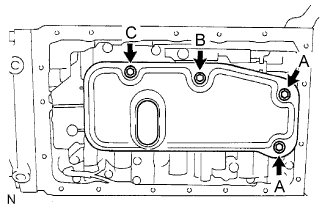
Install the oil strainer with the 4 bolts.
- Torque:
- 11 N*m { 110 kgf*cm, 8 ft.*lbf }
Tech Tips
Each bolt length is indicated below.
Bolt length 14 mm (0.55 in.) for A 20 mm (0.79 in.) for B 23 mm (0.91 in.) for C
-
-
INSTALL AUTOMATIC TRANSMISSION OIL PAN SUB-ASSEMBLY
Tech Tips
Remove any packing material and be careful not to spill oil on the contacting surfaces of the transmission case and oil pan.
-
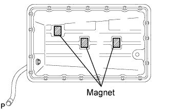
Install the 3 magnets to the locations indicated in the illustration.
-
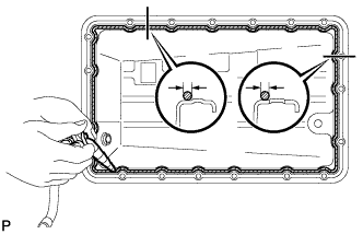
Apply seal packing to the oil pan as shown in the illustration.
Seal packing Toyota Genuine Seal Packing 1281, Three Bond 1281 or equivalent -
Install the oil pan with the 19 bolts.
- Torque:
- 7.4 N*m { 75 kgf*cm, 65 in.*lbf }
-
-
INSTALL TRANSMISSION OIL FILLER TUBE SUB-ASSEMBLY
-
Coat a new O-ring with ATF, and install it to the oil filler tube.
-
Install the oil filler tube with the 2 bolts.
- Torque:
- 12 N*m { 122 kgf*cm, 9 ft.*lbf }
-
Install the oil dipstick.
-
-
CONNECT CABLE TO NEGATIVE BATTERY TERMINAL
-
PERFORM INITIALIZATION
-
Perform initialization Click here.
Note
Certain systems need to be initialized after disconnecting and reconnecting the cable from the negative (-) battery terminal.
-
-
ADD AUTOMATIC TRANSMISSION FLUID
-
Add automatic transmission fluid Click here.
Fluid type Toyota Genuine ATF TYPE T-IV
-
-
INSPECT AUTOMATIC TRANSMISSION FLUID
-
Inspect the automatic transmission fluid Click here.
-