AUTOMATIC TRANSMISSION SYSTEM, Diagnostic DTC:P2716/77

| DTC Code | DTC Name |
|---|---|
| P2716/77 | Pressure Control Solenoid "D" Electrical (Shift Solenoid Valve SLT) |
DESCRIPTION
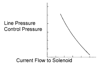
The throttle pressure that is applied to the primary regulator valve (which modulates the line pressure) causes the solenoid valve SLT, under electronic control, to precisely modulate and generate the line pressure according to the extent that the accelerator pedal is depressed or the output of engine power.
This controls the line pressure and provides smooth shifting characteristics.
Upon receiving a signal of the throttle valve opening angle, the ECM controls the line pressure by sending a predetermined duty ratio* to the solenoid valve, modulating the line pressure and generating throttle pressure.
Tech Tips
*: The duty ratio is the ratio of the current ON time (A) to the total of the current ON and OFF time (A + B).
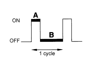
Duty Ratio (%) = A / (A + B) x 100
| DTC No. | DTC Detection Condition | Trouble Area |
|---|---|---|
| P2716/77 | ECM detects shift solenoid valve SLT circuit malfunction for 1 sec. or more (1 trip detection logic) |
|
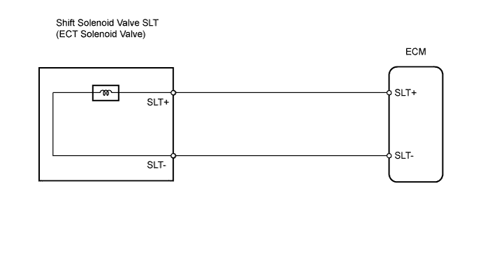
WIRING DIAGRAM
INSPECTION PROCEDURE
PROCEDURE
-
INSPECT TRANSMISSION WIRE (SHIFT SOLENOID VALVE SLT)
-
Disconnect the E1 wire connector.
-
Measure the resistance of the transmission wire.
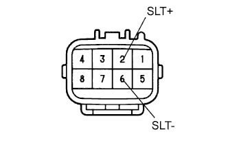
Standard resistance Tester Connection Condition Specified Condition 2 (SLT+) - 6 (SLT-) 20°C (68°F) 5.0 to 5.6 Ω 2 (SLT+) - Body ground 20°C (68°F) 10 kΩ or higher 6 (SLT-) - Body ground 20°C (68°F) 10 kΩ or higher
NG 
INSPECT SHIFT SOLENOID VALVE SLT Click here
OK 
-
-
CHECK WIRE HARNESS (TRANSMISSION WIRE - ECM)
-
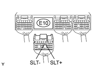
Disconnect the E10 ECM connector.
-
Measure the resistance of the wire harness side connector.
Standard resistance Tester Connection Condition Specified Condition E10-12 (SLT+) - E10-13 (SLT-) 20°C (68°F) 5.0 to 5.6 Ω E10-12 (SLT+) - Body ground 20°C (68°F) 10 kΩ or higher E10-13 (SLT-) - Body ground 20°C (68°F) 10 kΩ or higher
NG 
REPAIR OR REPLACE HARNESS AND CONNECTOR
OK 
REPLACE ECM
-
-
INSPECT SHIFT SOLENOID VALVE SLT
-
Remove the shift solenoid valve SLT.
-
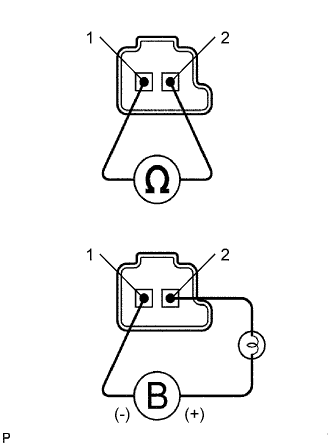
Measure the resistance between the solenoid valve terminal and solenoid valve body.
Standard resistance 5.0 to 5.6 Ωat 20°C (68°F) -
Connect the positive (+) lead with a 21 W bulb to terminal 2 and the negative (-) lead to terminal 1 of the solenoid valve connector, then check the movement of the valve.
-
Check the operating noise of terminal 1 of the solenoid valve.
OK Solenoid makes operating noise. Tech Tips
Reference: Inspect using an oscilloscope.
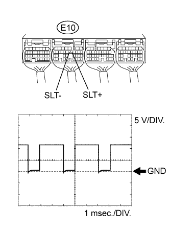
Check the waveform of the ECM connector.
OK Refer to illustration Item Content Tester Connection E10-12 (SLT+) - E10-13 (SLT-) Tool Setting 5 V/DIV., 1 msec./DIV. Condition Engine idle speed
NG
REPLACE SHIFT SOLENOID VALVE SLT
OK
REPAIR OR REPLACE TRANSMISSION WIRE
-