AUTOMATIC TRANSMISSION SYSTEM, Diagnostic DTC:P0973/62, P0974/62, P0976/63, P0977/63

| DTC Code | DTC Name |
|---|---|
| P0973/62 | Shift Solenoid "A" Control Circuit Low (Shift Solenoid Valve S1) |
| P0974/62 | Shift Solenoid "A" Control Circuit High (Shift Solenoid Valve S1) |
| P0976/63 | Shift Solenoid "B" Control Circuit Low (Shift Solenoid Valve S2) |
| P0977/63 | Shift Solenoid "B" Control Circuit High (Shift Solenoid Valve S2) |
DESCRIPTION
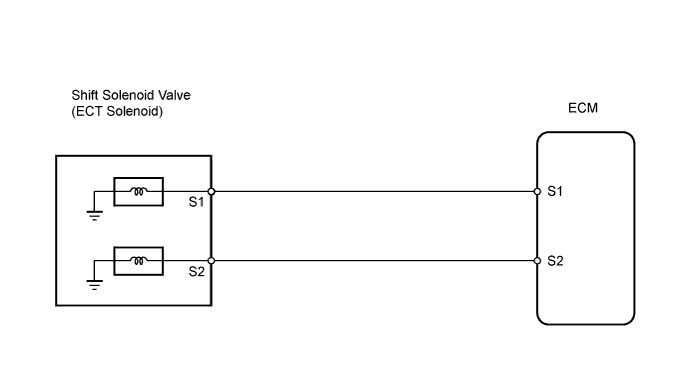
Shifting from 1st to O/D is performed in combination with the ON and OFF operation of the shift solenoid valves S1 and S2 controlled by the ECM. If an open or short circuit occurs in either of the shift solenoid valves, the ECM controls the remaining normal shift solenoid valve to allow the vehicle to be operated safely (fail-safe function).
Fail-safe function:
If either of the shift solenoid valve circuits develops an open or short, the ECM turns the other shift solenoid ON and OFF to shift to the gear positions shown in the table below. The ECM also turns the shift solenoid valve SL OFF at the same time. If both solenoids are malfunctioning, electronic hydraulic control does not operate and must be performed manually. Manual shifting as shown in the following table must be performed.
In case of a short circuit, the ECM stops sending current to the circuit.
| Position | Normal | Shift Solenoid S1 Malfunctioning | Shift Solenoid S2 Malfunctioning | Both Solenoids Malfunctioning | ||||||
|---|---|---|---|---|---|---|---|---|---|---|
| Solenoid valve | Gear | Solenoid valve | Gear | Solenoid valve | Gear | Gear when shift selector is manually operated | ||||
| S1 | S2 | S1 | S2 | S1 | S2 | |||||
| D | ON | OFF | 1st | X | ON | 3rd | ON | X | 1st | O/D |
| ON | ON | 2nd | X | ON | 3rd | OFF | X | O/D | O/D | |
| OFF | ON | 3rd | X | ON | 3rd | OFF | X | O/D | O/D | |
| OFF | OFF | O/D | X | OFF | O/D | OFF | X | O/D | O/D | |
| 2 | ON | OFF | 1st | X | ON | 3rd | ON | X | 1st | 3rd |
| ON | ON | 2nd | X | ON | 3rd | OFF | X | 3rd | 3rd | |
| OFF | ON | 3rd | X | ON | 3rd | OFF | X | 3rd | 3rd | |
| L | ON | OFF | 1st | X | OFF | 1st | ON | X | 1st | 1st |
| ON | ON | 2nd | X | ON | 2nd | ON | X | 1st | 1st | |
Tech Tips
X: Malfunction
| DTC No. | DTC Detection Condition | Trouble Area |
|---|---|---|
| P0973/62 | ECM detects short in solenoid valve S1 circuit 4 times when solenoid valve S1 is operated (1 trip detection logic) |
|
| P0974/62 | ECM detects open in solenoid valve S1 circuit 4 times when solenoid valve S1 is not operated (1 trip detection logic) |
|
| P0976/63 | ECM detects short in solenoid valve S2 circuit 4 times when solenoid valve S2 is operated (1 trip detection logic) |
|
| P0977/63 | ECM detects open in solenoid valve S2 circuit 4 times when solenoid valve S2 is not operated (1 trip detection logic) |
|
MONITOR DESCRIPTION
The ECM controls gear shift by turning the shift solenoid valves ON/OFF. When there is an open or short circuit in any shift solenoid valve circuit, the ECM detects the problem, illuminates the MIL and stores a DTC.
The ECM performs the fail-safe function and turns the normally functioning shift solenoid valve ON/OFF.
In case of an open or short circuit, the ECM stop sending current to the circuit.
WIRING DIAGRAM
INSPECTION PROCEDURE
PROCEDURE
-
INSPECT TRANSMISSION WIRE (SHIFT SOLENOID VALVE S1/S2)
-
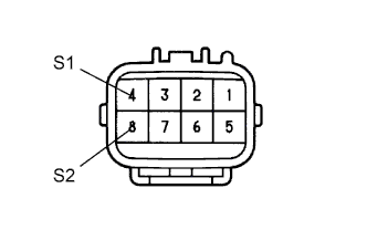
Disconnect the E1 wire connector.
-
Measure the resistance of the transmission wire.
Standard resistance Tester Connection Condition Specified Condition 4 (S1) - Body ground 20°C (68°F) 11 to 15 Ω 8 (S2) - Body ground 20°C (68°F) 11 to 15 Ω
NG 
INSPECT SHIFT SOLENOID VALVE S1/S2 Click here
OK 
-
-
CHECK WIRE HARNESS (TRANSMISSION WIRE - ECM)
-
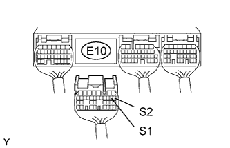
Disconnect the E10 ECM connector.
-
Measure the resistance of the wire harness side connector.
Standard resistance Tester Connection Condition Specified Condition E10-9 (S1) - Body ground 20°C (68°F) 11 to 15 Ω E10-8 (S2) - Body ground 20°C (68°F) 11 to 15 Ω
NG 
REPAIR OR REPLACE HARNESS AND CONNECTOR
OK 
REPLACE ECM
-
-
INSPECT SHIFT SOLENOID VALVE S1/S2
-
Remove the shift solenoid valve S1/S2.
-
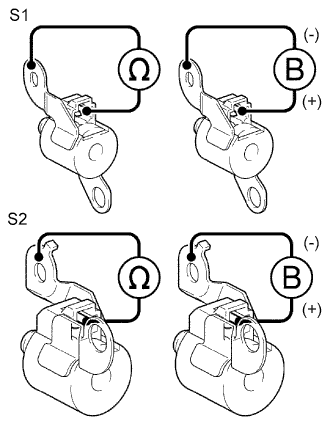
Measure the resistance between the solenoid valve terminal and solenoid valve body.
Standard resistance 11 to 15 Ωat 20°C (68°F) -
Connect the battery's positive (+) lead to the terminal of the solenoid connector, and the negative (-) lead to the solenoid body.
-
Check the operating noise of the solenoid valve.
OK Solenoid makes operating noise.
NG
REPLACE SHIFT SOLENOID VALVE S1/S2
OK
REPAIR OR REPLACE TRANSMISSION WIRE
-