AUTOMATIC TRANSMISSION SYSTEM, Diagnostic DTC:P0722/61

| DTC Code | DTC Name |
|---|---|
| P0722/61 | Output Speed Sensor Circuit No Signal |
DESCRIPTION
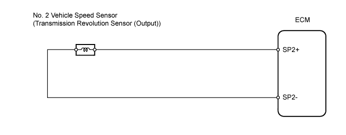
The No. 2 vehicle speed sensor (SP2) detects the rotation speed of the transmission output shaft and sends signals to the ECM. The ECM determines the vehicle speed based on these signals.
AC voltage is generated in the No. 2 vehicle speed sensor (SP2) coil as the rotor mounted on the output shaft rotates, and this voltage is sent to the ECM.
The gear shift point and lock-up timing are controlled by the ECM based on the signals from the output speed sensor and throttle position sensor.
| DTC No. | DTC Detection Condition | Trouble Area |
|---|---|---|
| P0722/61 |
|
|
MONITOR DESCRIPTION
The output speed sensor (SP2) monitors the output shaft speed. The ECM controls the gear shift point and the lock-up timing based on the signals from the output speed sensor (SP2) and throttle position sensor.
If the ECM detects no signal from the output speed sensor (SP2) even while the vehicle is moving, the ECM will conclude that the output shaft speed sensor (SP2) is malfunctioning. The ECM will illuminate the MIL and set the DTC.
WIRING DIAGRAM
INSPECTION PROCEDURE
PROCEDURE
-
CHECK SPEED SENSOR (INSTALLATION)
-
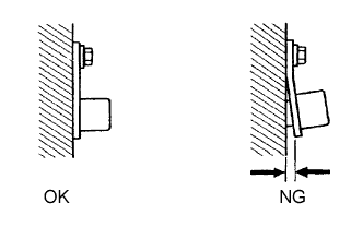
Check the speed sensor installation.
OK Installation bolt is tightened properly and there is no clearance between sensor and transmission case.
NG 
SECURELY INSTALL SPEED SENSOR OR REPLACE SPEED SENSOR
OK 
-
-
INSPECT NO. 2 VEHICLE SPEED SENSOR
-
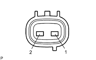
Disconnect the T8 sensor connector from the transmission.
-
Measure the resistance of the sensor.
Standard resistance Tester Connection Condition Specified Condition 1 - 2 20°C (68°F) 560 to 680 Ω Tech Tips
Reference: Inspect using an oscilloscope.
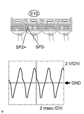
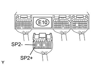
Check the waveform of the ECM connector.
OK Refer to illustration Item Content Tester Connection E10-35 (SP2+) - E10-27 (SP2-) Tool Setting 2 V/DIV., 2 msec./DIV. Condition Vehicle speed 20 km/h (12 mph)
NG
REPLACE NO. 2 VEHICLE SPEED SENSOR
OK
-
-
CHECK WIRE HARNESS (NO. 2 VEHICLE SPEED SENSOR - ECM)
-
Disconnect the E10 ECM connector.
-
Measure the resistance of the wire harness side connector.
Standard resistance Tester Connection Condition Specified Condition E10-35 (SP2+) - E10-27 (SP2-) 20°C (68°F) 560 to 680 Ω E10-35 (SP2+) - Body ground 20°C (68°F) 10 kΩ or higher E10-27 (SP2-) - Body ground 20°C (68°F) 10 kΩ or higher
NG
REPAIR OR REPLACE HARNESS AND CONNECTOR
OK 
REPLACE ECM
-