AUTOMATIC TRANSMISSION ASSEMBLY INSTALLATION

-
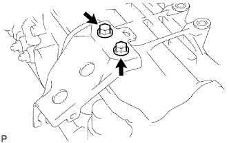
INSTALL TRANSMISSION CONTROL CABLE BRACKET
-
Install the control cable bracket with the 2 bolts.
- Torque:
- 28 N*m { 286 kgf*cm, 21 ft.*lbf }
-
-
INSPECT TORQUE CONVERTER CLUTCH ASSEMBLY
-
Inspect the torque converter clutch Click here.
-
-
INSTALL TORQUE CONVERTER CLUTCH ASSEMBLY
-
Install the torque converter clutch to the automatic transmission.
-
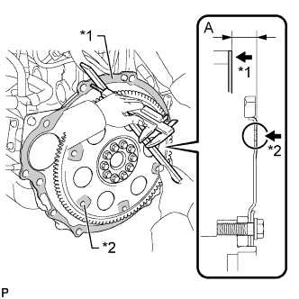
Using a vernier caliper and straightedge, measure dimension A between the surface of the engine that contacts the transmission*1, and the surface of the drive plate that contacts the converter*2. #
-
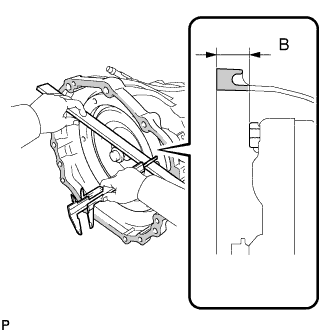
Using a vernier caliper and straightedge, measure dimension B shown in the illustration. Check that B is greater than A measured in step #.
Standard dimension B = A + 1.00 mm (0.0394 in.) or more
-
-
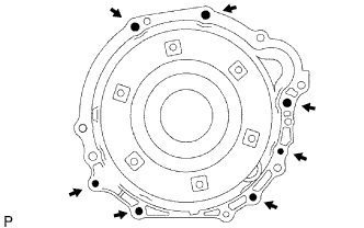
INSTALL AUTOMATIC TRANSMISSION ASSEMBLY
-
Install the transmission to the engine with the 7 bolts.
- Torque:
- 71 N*m { 724 kgf*cm, 52 ft.*lbf, for 17mm head }
- 37 N*m { 377 kgf*cm, 27 ft.*lbf, for 14 mm head }
Note
Confirm that the 2 knock pins are installed to the surface of the engine cylinder block that contacts the transmission before installing the transmission.
-
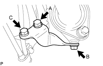
Install the exhaust manifold stay with the 3 bolts.
- Torque:
- 44 N*m { 449 kgf*cm, 32 ft.*lbf, for bolt A }
- 30 N*m { 306 kgf*cm, 22 ft.*lbf, for bolt B }
- 71 N*m { 724 kgf*cm, 52 ft.*lbf, for bolt C }
-
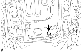
Hold the crankshaft pulley bolt with a wrench and install the 6 torque converter clutch mounting bolts.
- Torque:
- 41 N*m { 418 kgf*cm, 30 ft.*lbf }
Note
Install the black bolt first, and then install the silver bolts.
-
-
INSTALL FLYWHEEL HOUSING DUST SEAL
-
CONNECT WIRE HARNESS
-
CONNECT CONNECTOR
-
Connect the park/neutral position switch connector, transmission wire connector, ATF temperature sensor connector and 3 speed sensor connectors.
-
Attach the 4 harness clamps.
-
Install the heat insulator to the park/neutral position switch with the 2 bolts.
- Torque:
- 7.5 N*m { 76 kgf*cm, 66 in.*lbf }
-
Tilt up the transmission.
-
-
INSTALL NO. 1 ENGINE MOUNTING INSULATOR REAR
-
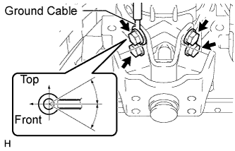
Install the engine mounting insulator and ground cable to the transmission with the 4 bolts.
- Torque:
- 47 N*m { 479 kgf*cm, 35 ft.*lbf }
Tech Tips
The acceptable installation angle of the ground cable is within 30° upward or downward from the horizontal position.
-
-
INSTALL NO. 3 FRAME CROSSMEMBER SUB-ASSEMBLY
-
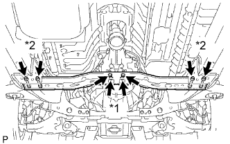
*1: Install the 4 set bolts of the engine mounting insulator.
- Torque:
- 27 N*m { 275 kgf*cm, 20 ft.*lbf }
-
*2: Install the frame crossmember with the 4 bolts and 4 nuts.
- Torque:
- 50 N*m { 510 kgf*cm, 37 ft.*lbf }
-
Connect the wire harness clamp to the No. 3 frame crossmember.
-
-
INSTALL STARTER ASSEMBLY
-
Install the starter assembly Click here.
-
-
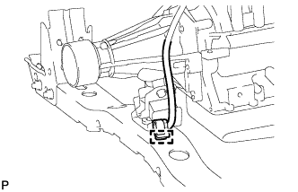
CONNECT TRANSMISSION CONTROL CABLE ASSEMBLY
-
Connect the control cable with the clip.
-
Connect the control cable with the nut.
- Torque:
- 14 N*m { 143 kgf*cm, 10 ft.*lbf }
-
-
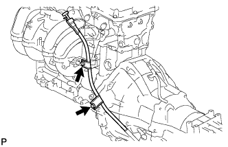
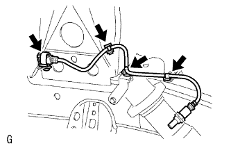
CONNECT OIL COOLER TUBE
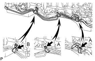
-
Loosely install the tip of the oil cooler tube inlet to the automatic transmission by hand.
-
Loosely install the tip of the oil cooler tube outlet to the automatic transmission by hand.
-
Install the 3 clamps with the 3 bolts.
- Torque:
- 5.0 N*m { 50 kgf*cm, 44 in.*lbf, for A }
- 12 N*m { 122 kgf*cm, 9 ft.*lbf, for B }
-
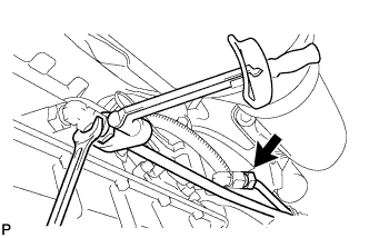
Using a union nut wrench, tighten the inlet and outlet tubes.
- Torque:
- 34 N*m { 346 kgf*cm, 25 ft.*lbf }
Note
Use the formula to calculate special torque values for situations where a union nut wrench is combined with a torque wrench Click here.
-
-
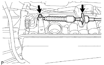
INSTALL TRANSMISSION OIL FILLER TUBE SUB-ASSEMBLY
-
Coat a new O-ring with ATF, and install it to the oil filler tube.
-
Install the oil filler tube with the 2 bolts.
- Torque:
- 12 N*m { 122 kgf*cm, 9 ft.*lbf }
-
Install the oil dipstick.
-
-
INSTALL PROPELLER WITH CENTER BEARING SHAFT ASSEMBLY
-
Install the propeller with center bearing shaft assembly Click here.
-
-
INSTALL FRONT EXHAUST PIPE ASSEMBLY
-
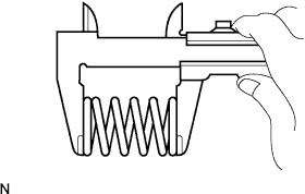
Using a vernier caliper, measure the free length of the compression spring.
Minimum length 40 mm (1.57 in.) If the length is less than the minimum, replace the compression spring.
-
Install the front pipe to the pipe support.
-
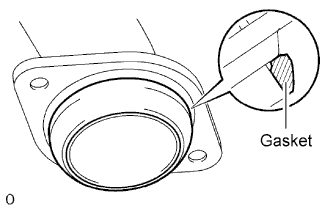
Install a new gasket to the outlet pipe.
Tech Tips
Using a plastic-faced hammer, uniformly strike the gasket so that the gasket and exhaust pipe are properly fit.
Note
-
Be careful with the installation direction of the gasket.
-
Do not reuse the gasket.
-
To ensure a proper seal, do not use the front pipe to force the gasket onto the outlet pipe.
-
-
Install the front pipe with the 2 compression springs and 2 bolts. Alternately tighten the bolts in several passes.
- Torque:
- 43 N*m { 438 kgf*cm, 32 ft.*lbf }
-
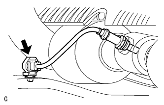
Connect the heated oxygen sensor connector.
-
Attach the 3 air fuel ratio sensor wire clamps to the vehicle body.
-
Connect the air fuel ratio sensor connector.
-
Connect the front pipe to the center pipe with a new gasket, 2 bolts and 2 nuts. Alternately tighten the bolts in several passes.
- Torque:
- 48 N*m { 489 kgf*cm, 35 ft.*lbf }
Note
Do not reuse the gasket.
-
-
ADJUST SHIFT LEVER POSITION
-
Remove the nut and disconnect the control cable.
-
Remove the clip and disconnect the control cable from the control cable bracket.
-
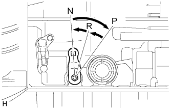
Push the control shaft rearward as much as possible.
-
Return the control shaft lever 2 notches to the N position.
-
While holding the control shaft lever slightly toward the R position side, tighten the nut.
- Torque:
- 14 N*m { 143 kgf*cm, 10 ft.*lbf }
-
-
ADD AUTOMATIC TRANSMISSION FLUID
Fluid type Toyota Genuine ATF Type T-IV -
CONNECT CABLE TO NEGATIVE BATTERY TERMINAL
-
PERFORM INITIALIZATION
-
Perform initialization Click here.
Note
Certain systems need to be initialized after disconnecting and reconnecting the cable to the negative (-) battery terminal.
-
-
INSPECT SHIFT LEVER POSITION
-
When moving the shift lever from P to R with the ignition switch ON and the brake pedal depressed, make sure that the shift lever moves smoothly and correctly into position.
-
Start the engine and make sure that the vehicle moves forward after moving the shift lever from N to D, and moves rearward after shifting to the.
If the results are not as specified, inspect the park/neutral position switch and check the shift lever.
-
-
CHECK FOR EXHAUST GAS LEAKS
-
INSPECT AUTOMATIC TRANSMISSION FLUID
-
Inspect the automatic transmission fluid Click here.
-