AUTOMATIC TRANSMISSION SYSTEM, Diagnostic DTC:P0717/67

| DTC Code | DTC Name |
|---|---|
| P0717/67 | Input Speed Sensor Circuit No Signal |
DESCRIPTION
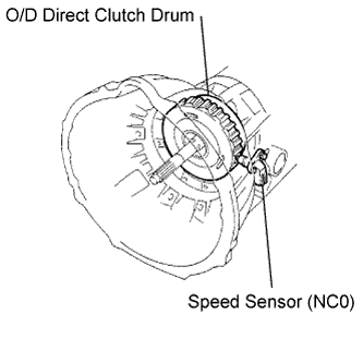
The speed sensor (NC0) detects the rotation speed of the O/D input shaft from the rotation speed of the O/D direct clutch drum. Its construction is the same as that of the speed sensor (SP2).
By comparing the speed sensor (NC0) signal with the speed sensor (SP2) signal, the ECM detects the shift timing of the gears and controls the engine torque and hydraulic pressure according to various conditions. As a result, the gears shift smoothly.
| DTC No. | DTC Detection Condition | Trouble Area |
|---|---|---|
| P0717/67 |
|
|
MONITOR DESCRIPTION
The input speed sensor (NC0) detects the transmission input shaft speed. The ECM determines the gear shift timing based on a comparison of the input speed sensor (NC0) (input shaft speed) with the output speed sensor (output shaft speed).
When the output shaft speed is higher than the expected value and the input shaft speed is 300 rpm or less while the vehicle is running with the shift lever on D, the ECM will conclude that there is a malfunction in the input speed sensor (NC0). The ECM will illuminate the MIL and set the DTC.
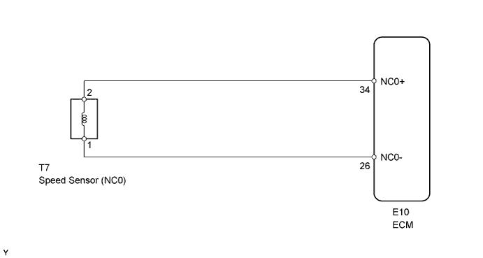
WIRING DIAGRAM
INSPECTION PROCEDURE
PROCEDURE
-
CHECK SPEED SENSOR (NC0) (INSTALLATION)
-
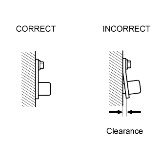
Check the speed sensor installation.
OK Installation bolt is tightened properly and there is no clearance between sensor and transmission case.
NG 
SECURELY INSTALL SPEED SENSOR OR REPLACE SPEED SENSOR
OK 
-
-
INSPECT SPEED SENSOR (NC0)
-
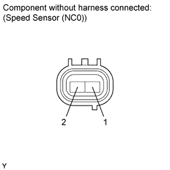
Disconnect the T7 sensor connector from the transmission.
-
Measure the resistance of the sensor.
Standard resistance Tester Connection Condition Specified Condition 1 - 2 20°C (68°F) 560 to 680 Ω Tech Tips
Reference: Inspect using an oscilloscope.
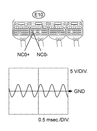
Check the waveform of the ECM connector.
OK Refer to illustration Item Content Tester Connection E10-34 (NC0+) - E10-26 (NC0-) Tool Setting 5 V/DIV, 0.5 msec./DIV. Condition Engine is idling
NG
REPLACE SPEED SENSOR
OK
-
-
CHECK WIRE HARNESS (SPEED SENSOR (NC0) - ECM)
-
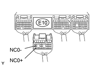
Disconnect the E10 ECM connector.
-
Measure the resistance of the wire harness side connector.
Standard resistance Tester Connection Condition Specified Condition E10-34 (NC0+) - E10-26 (NC0-) 20°C (68°F) 560 to 680 Ω E10-34 (NC0+) - Body ground 20°C (68°F) 10 kΩ or higher E10-26 (NC0-) - Body ground 20°C (68°F) 10 kΩ or higher
NG
REPAIR OR REPLACE HARNESS AND CONNECTOR
OK 
REPLACE ECM
-