AUTOMATIC TRANSMISSION UNIT REASSEMBLY

-
BEARING POSITION
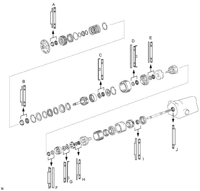
Bearing diameter Mark Front Race Diameter
Inside / Outside
Thrust Bearing Diameter
Inside / Outside
Rear Race Diameter
Inside / Outside
A 28.45 mm (1.120 in.) / 47.3 mm (1.862 in.) 29.2 mm (1.15 in.) / 50.2 mm (1.976 in.) - B 28.6 mm (1.126 in.) / 46.4 mm (1.827 in.) 28.9 mm (1.138 in.) / 50.2 mm (1.976 in.) - C 33.0 mm (1.299 in.) /50.4 mm (1.984 in.) 31.4 mm (1.236 in.) / 49.4 mm (1.945 in.) - D 37.2 mm (1.465 in.) / 58.8 mm (2.315 in.) 33.8 mm (1.331 in.) / 50.0 mm (1.969 in.) - E 36.8 mm (1.449 in.) / 50.9 mm (2.004 in.) 33.7 mm (1.327 in.) / 47.6 mm (1.874 in.) - F 26.0 mm (1.024 in.) / 48.9 mm (1.925 in.) 26.0 mm (1.024 in.) / 42.8 mm (1.685 in.) 26.8 mm (1.055 in.) / 53.67 mm (2.113 in.) G - 35.2 mm (1.386 in.) /53.6 mm (2.110 in.) 34.3 mm (1.350 in.) / 47.8 mm (1.882 in.) H 33.7 mm (1.327 in.) / 47.6 mm (1.874 in.) 35.5 mm (1.398 in.) / 47.7 mm (1.878 in.) - I 28.5 mm (1.122 in.) / 44.2 mm (1.740 in.) 27.7 mm (1.091 in.) / 44.2 mm (1.740 in.) - J - 39.38 mm (1.550 in.) / 58.1 mm (2.287 in.) - -
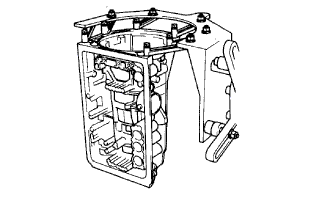
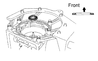
FIX TRANSMISSION CASE
-
Install the transmission case in the overhaul attachment.
-
-
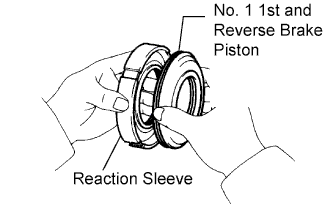
INSTALL NO. 1 1ST AND REVERSE BRAKE PISTON
-
Coat 2 new O-rings with ATF.
-
Install the 2 O-rings on the No. 1 brake piston.
-
Install the No. 1 brake piston to the reaction sleeve.
-
-
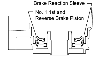
INSTALL BRAKE REACTION SLEEVE
-
Coat a new O-ring with ATF, and install it to the reaction sleeve.
-
With the No. 1 brake piston underneath (the rear side), install the brake reaction sleeve and No. 1 brake piston to the transmission case.
Note
Be careful not to damage the O-rings.
-
-
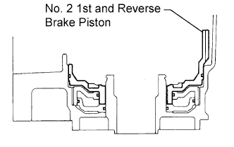
INSTALL NO. 2 1ST AND REVERSE BRAKE PISTON
-
Coat a new O-ring with ATF.
-
Install the O-ring on brake piston.
-
With the spring seat of the piston facing upward (the front side), place the piston in the transmission case.
Note
Be careful not to damage the O-ring.
-
-
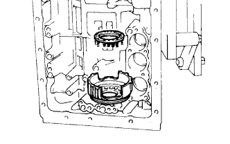
INSTALL 1ST AND REVERSE BRAKE RETURN SPRING SUB-ASSEMBLY
-
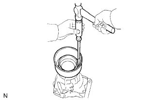
Place the No. 2 brake return spring onto the brake piston.
-
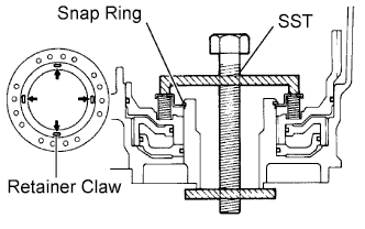
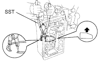
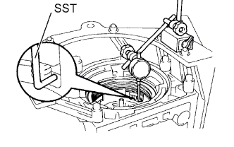
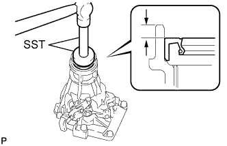
Place SST on the brake return spring, and compress the brake return spring.
- SST
- 09350-30020 ( 09350-07050 )
-
Using SST, install the snap ring. Make sure the end gap of the snap ring is not aligned with the spring retainer claw.
- SST
- 09350-30020 ( 09350-07070 )
-
-
INSPECT PISTON STROKE OF 1ST AND REVERSE BRAKE
-
Make sure the 1st and reverse brake pistons move smoothly when compressed air is applied into the transmission case.
-
-
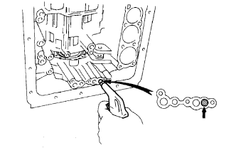
INSTALL LEAF SPRING
-
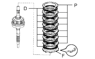
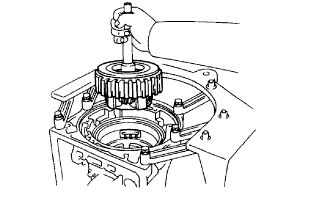
INSTALL REAR PLANETARY GEAR ASSEMBLY
-
Install the flange with the rounded edge facing upward.
-
Install the 7 discs and 7 plates.
Install in order F - D - P - D - P - D - P - D - P - D - P - D - P - D - P Tech Tips
F = Flange
P = Plate
D = Disc
-
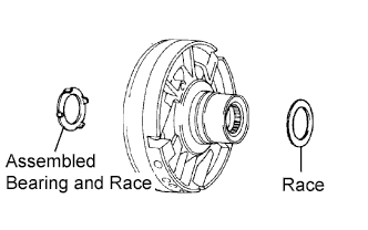
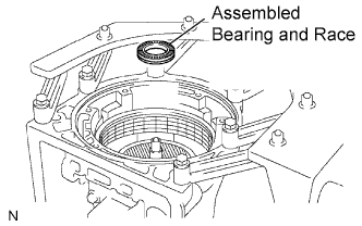
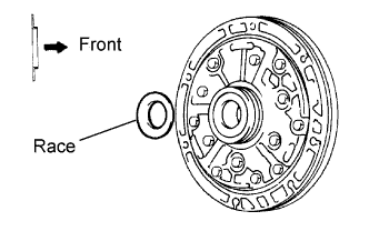
Coat the assembled bearing and race with petroleum jelly, and install it onto the case.
Standard assembled bearing and race diameter Item Inside Outside Assembled bearing and race 39.38 mm (1.550 in.) 58.1 mm (2.287 in.) Note
Be careful of the installation direction of the assembled bearing and race.
-
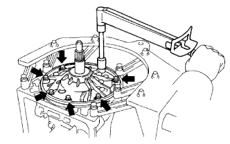
Align the teeth on the flange, discs and plates.
-
Face the snap ring upward (front side), and install the 2nd brake drum to the planetary gear.
Note
Face the oil hole in the drum towards the lower side of the transmission case (the side where the valve body is installed).
-
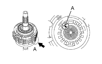
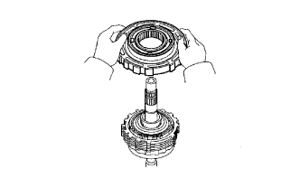
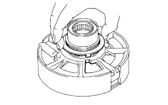
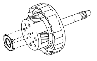
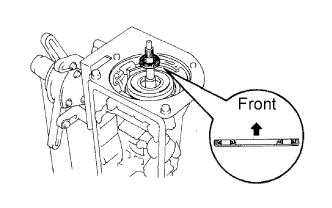
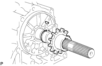
Align the splines of the transmission case with the assembled rear planetary gear and 1st and reverse brake with the output shaft, indicated by A.
-
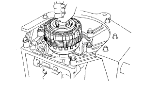
Install the assembled output shaft.
-
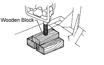
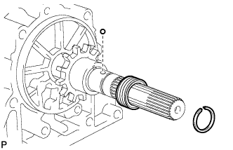
Reset the output shaft on wooden blocks.
-
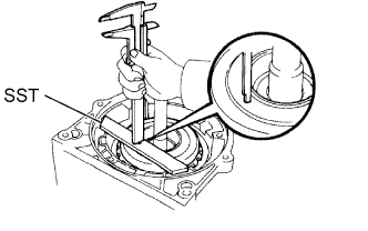
Using SST, install the snap ring.
- SST
- 09350-30020 ( 09350-07060 )
-
-
INSPECT PACK CLEARANCE OF 1ST AND REVERSE BRAKE
-
Using a feeler gauge, measure the clearance between the plate and 2nd brake drum.
Standard clearance 0.70 to 1.22 mm (0.0276 to 0.048 in.) If the clearance is not as specified, select another flange.
Tech Tips
There are 8 different thicknesses for the flange.
Standard flange thickness No. Specified Condition No. Specified Condition 67 5.4mm (0.213 in.) 52 4.6 mm (0.181 in.) 66 5.2 mm (0.205 in.) 53 4.4 mm (0.173 in.) 50 5.0 mm (0.197 in.) 54 4.2 mm (0.165 in.) 51 4.8 mm (0.189 in.) 55 4.0 mm (0.157 in.)
-
-
INSTALL 2ND BRAKE PISTON SLEEVE
-
INSTALL BRAKE DRUM GASKET
-
Coat a new gasket with ATF, and install the brake drum gasket.
-
-
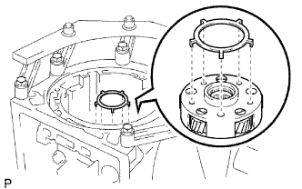
INSTALL NO. 1 ONE-WAY CLUTCH
-
Install the thrust washer onto the 2nd brake piston sleeve.
-
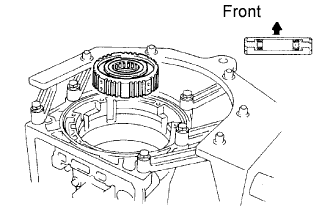
Install the No. 1 one-way clutch as shown in the illustration.
-
-
INSTALL 2ND BRAKE PACK

-
Install the 1.8 mm (0.071 in.) thick plate with the rounded edge side of the plate facing the disc.
-
Install the flange, 5 plates and 5 discs.
Install in order P - D - P - D - P - D - P - D - P - D - F Tech Tips
F = Flange
P = Plate
D = Disc
-
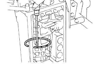
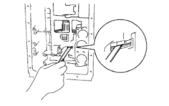
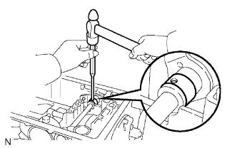
Using a screwdriver, install the snap ring.
-
-
INSPECT PACK CLEARANCE OF 2ND BRAKE
-
Using a feeler gauge, measure the clearance between the snap ring and flange.
Standard clearance 0.62 to 1.98 mm (0.0244 to 0.0780 in.) If the clearance is not as specified, inspect the discs.
-
-
INSTALL PLANETARY SUN GEAR ASSEMBLY AND ONE-WAY CLUTCH ASSEMBLY
-
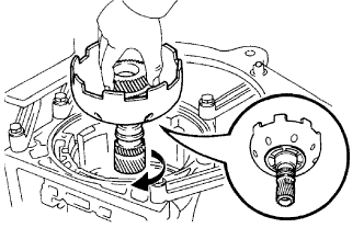
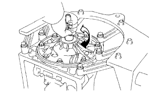
While turning the sun gear clockwise, install it into the one-way clutch.
Tech Tips
Confirm that the thrust washer is installed correctly.
-
-
INSTALL FRONT PLANETARY GEAR
-
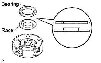
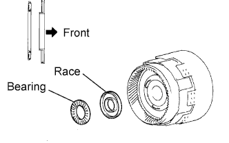
Coat the bearing and race with petroleum jelly, and install them onto the planetary gear.
Standard bearing and race diameter Item Inside Outside Bearing 35.5 mm (1.398 in.) 47.7 mm (1.878 in.) Race 33.7 mm (1.327 in.) 47.6 mm (1.874 in.) Note
Be careful of the installation direction of the bearing and race.
-
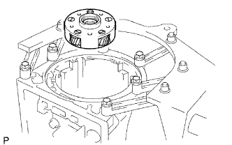
Install the planetary gear to the sun gear input drum.
-
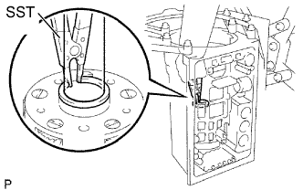
Using SST, install the snap ring.
- SST
- 09350-30020 ( 09350-07070 )
-
Remove the wooden blocks under the output shaft.
-
Coat the race with petroleum jelly, and install it onto the planetary gear.
Standard race diameter Item Inside Outside Race 34.3 mm (1.350 in.) 47.8 mm (1.882 in.) Note
Be careful to the installation direction of the race.
-
-
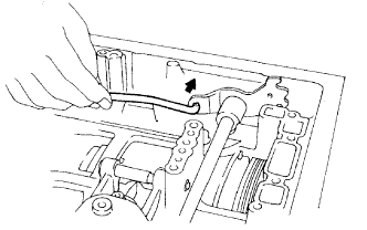
INSTALL 2ND COAST BRAKE BAND
-
Install the brake band to the case.
-
Install the E-ring to the pin.
-
Install the pin through the brake band.
-
-
INSTALL DIRECT CLUTCH ASSEMBLY
-
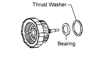
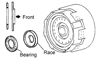
Install the assembled bearing and race and thrust washer to the forward clutch.
-
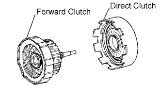
Install the direct clutch to the forward clutch.
-
-
INSTALL FRONT PLANETARY RING GEAR
-
Coat the race with petroleum jelly, and install them onto the forward clutch.
Standard bearing and race diameter Item Inside Outside Bearing 26.0 mm (1.024 in.) 42.8 mm (1.685 in.) Race 26.0 mm (1.024 in.) 48.9 mm (1.925 in.) Note
Be careful of the installation direction of the bearing and race.
-
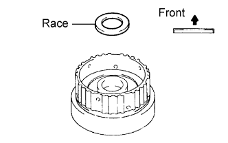
Coat the race with petroleum jelly, and install it onto the front planetary ring gear.
Standard race diameter Item Inside Outside Race 26.8 mm (1.055 in.) 53.67 mm (2.113 in.) Note
Be careful of the installation direction of the race.
-
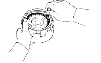
Align the flukes of the discs in the forward clutch.
-
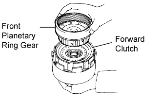
Align the splines of the planetary ring gear with the flukes of the discs and install the planetary ring gear to the forward clutch.
-
-
INSTALL FORWARD CLUTCH ASSEMBLY
-
Coat the bearing and race with petroleum jelly, and install them onto the ring gear.
Standard bearing and race diameter Item Inside Outside Bearing 49.9 mm (1.965 in.) 64.4 mm (2.535 in.) Race 53.4 mm (2.102 in.) 63.6 mm (2.504 in.) Note
Be careful of the installation direction of the bearing and race.
-
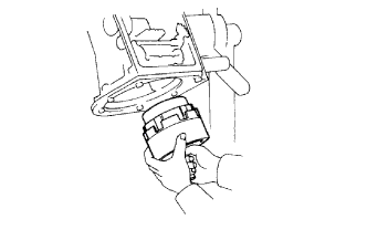
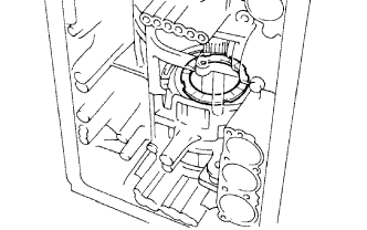
Install the assembled direct clutch, forward clutch and front planetary ring gear into the transmission case.
-
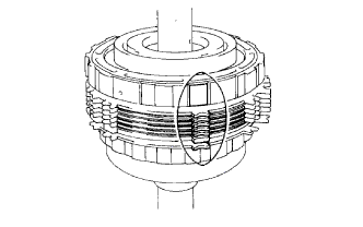
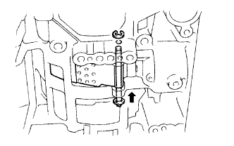
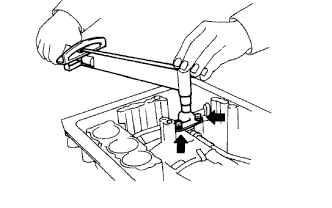
Using a vernier caliper, measure the distance between the sun gear input drum and direct clutch drum as shown in the illustration.
Standard distance 5.3 to 7.3 mm (0.209 to 0.287 in.) If the distance is not as specified, check for an improper installation.
-

Coat the assembled bearing and race with petroleum jelly and install it onto the forward clutch.
Standard assembled bearing and race diameter Item Inside Outside Assembled bearing and race 33.7 mm (1.327 in.) 47.6 mm (1.874 in.) Note
Be careful of the installation direction of the assembled bearing and race.
-
-
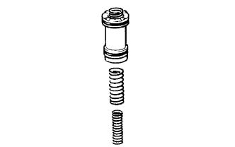
INSTALL 2ND COAST BRAKE PISTON ASSEMBLY
-
Coat 2 new O-rings with ATF, and install them to the cover.
-
Install the spring, piston assembly and cover to the case.
-
Using SST, install the snap ring.
- SST
- 09350-30020 ( 09350-07060 )
-
-
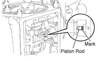
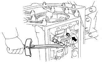
INSPECT PISTON STROKE OF 2ND COAST BRAKE
-
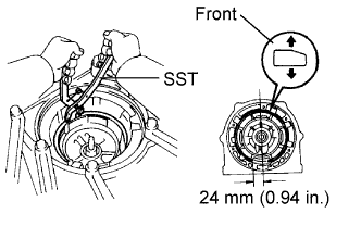
Place a mark on the 2nd coast brake piston rod.
-
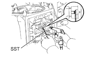
Using SST, measure the stroke while applying and releasing compressed air (392 kPa (4.0 kgf/cm2, 57 psi)).
- SST
- 09240-00020
If the stroke is not as specified, replace the brake band with a new one.
-
-
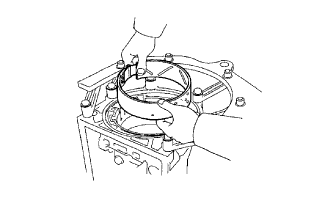
INSTALL OVERDRIVE BRAKE ASSEMBLY
-
Coat the assembled bearing and race and the race with petroleum jelly, and install them onto the overdrive brake assembly.
Standard assembled bearing and race and race diameter Item Inside Outside Race 36.8 mm (1.449 in.) 50.9 mm (2.004 in.) Assembled bearing and race 33.8 mm (1.331 in.) 50.0 mm (1.969 in.) Note
Be careful of the installation direction of the assembled bearing and race and the race.
-
Confirm that the thrust washer is installed correctly.
Tech Tips
Make sure that the tab of the washer fits into the hole on the overdrive brake assembly.
-
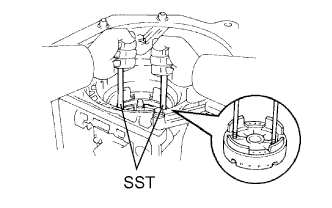
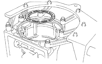
Using 2 bolts of SST, aim the bolt and oil holes of the overdrive brake assembly toward the valve body side, and align them with the bolt holes of the transmission case. Insert the overdrive brake assembly.
- SST
- 09350-30020 ( 09350-07020 )
-
Temporarily tighten the 2 bolts.
-
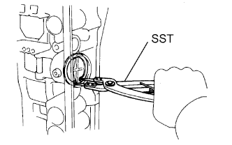
Using SST, install the snap ring.
- SST
- 09350-30020 ( 09350-07060 )
Tech Tips
Install the snap ring open end toward the valve body.
-
Tighten the 2 bolts.
- Torque:
- 25 N*m { 260 kgf*cm, 19 ft.*lbf }
-
-
INSPECT OUTPUT SHAFT
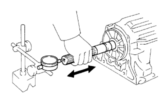
-
Using a dial indicator, measure the end play of the output shaft with hand.
Standard end play 0.30 to 1.04 mm (0.0118 to 0.0409 in.) If the end play is not as specified, check for an improper installation.
-
Check that the output shaft rotates smoothly.
-
-
INSTALL OVERDRIVE BRAKE CLUTCH DISC
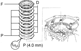
-
Install the 4.0 mm (0.157 in.) thick flange (flat ring) with the rounded edge side of the flange facing the discs.
-
Install the 5 plates, 5 discs and flange.
Install in order P - D - P - D - P - D - P - D - P - D - F Tech Tips
F = Flange
P = Plate
D = Disc
-
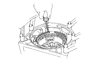
Using a screwdriver, install the snap ring.
-
-
INSPECT OVERDRIVE BRAKE PISTON
-
Place SST and a dial indicator onto the overdrive brake piston.
- SST
- 09350-30020 ( 09350-06120 )
-
Measure the stroke while applying and releasing compressed air (392 kPa (4.0 kgf/cm2, 57 psi)).
Standard piston stroke 1.75 to 2.05 mm (0.0689 to 0.0807 in.) If the piston stroke is not as specified, parts may have been assembled incorrectly. Check and reassemble again.
Tech Tips
-
If the piston stroke is still outside the standard even after reassembly, select another flange.
-
There are 7 different thicknesses for the flange.
Standard flange thickness No. Specified Condition No. Specified Condition 77 3.3 mm (0.130 in.) 81 3.8 mm (0.150 in.) 78 3.5 mm (0.138 in.) 82 3.9 mm (0.154 in.) 79 3.6 mm (0.142 in.) 83 4.0 mm (0.157 in.) 80 3.7 mm (0.146 in.) - - -
-
-
INSTALL OVERDRIVE PLANETARY RING GEAR
-
Coat the race with petroleum jelly, and install it onto the overdrive brake assembly.
Standard race diameter Item Inside Outside Race 37.2 mm (1.465 in.) 58.8 mm (2.315 in.) Note
Be careful of the installation direction of the race.
-
Install the ring gear.
-
Coat the assembled bearing and race with petroleum jelly, and install it onto the ring gear.
Standard assembled bearing and race diameter Item Inside Outside Assembled bearing and race 31.4 mm (1.236 in.) 49.4 mm (1.945 in.) Note
Be careful of the installation direction of the assembled bearing and race.
-
-
REMOVE OVERDRIVE PLANETARY GEAR ASSEMBLY AND DIRECT CLUTCH DRUM ASSEMBLY
-
Coat the race with petroleum jelly, and install it onto the planetary gear.
Standard race diameter Item Inside Outside Race 24.7 mm (0.972 in.) 41.8 mm (1.646 in.) Note
Be careful of the installation direction of the race.
-
Install the overdrive planetary gear, overdrive direct clutch and one-way clutch.
-
Place SST on the transmission case.
- SST
- 09350-36010 ( 09350-06090 )
-
Using a vernier caliper, measure the distance between the top of SST and clutch drum.
Standard distance 15.5 to 16.5 mm (0.610 to 0.650 in.) If the distance is not as specified, check for an improper installation.
-
Coat the assembled bearing and race with petroleum jelly, and install it onto the overdrive direct clutch.
Standard assembled bearing and race diameter Item Inside Outside Assembled bearing and race 29.2 mm (1.150 in.) 50.2 mm (1.976 in.) Note
Be careful of the installation direction of the assembled bearing and race.
-
-
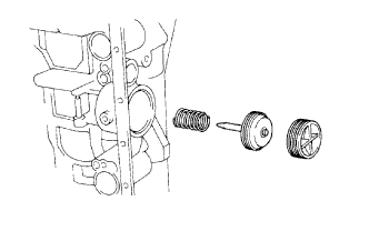
INSTALL OIL PUMP ASSEMBLY
-
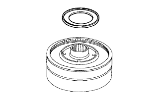
Coat the race with petroleum jelly, and install it onto the oil pump.
Standard race diameter Item Inside Outside Race 28.45 mm (1.120 in.) 47.3 mm (1.862 in.) Note
Be careful of the installation direction of the race.
-
Coat a new O-ring with ATF, and install it around the pump body.
-
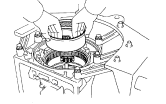
Place the oil pump through the input shaft, and align the bolt holes of the pump body with the transmission case.
-
Hold the input shaft, and lightly press the oil pump body to slide the oil seal rings into the overdrive direct clutch drum.
Note
Do not forcefully push on the oil pump as the oil seal ring will stick to the direct clutch drum.
-
Install the 7 bolts.
- Torque:
- 22 N*m { 220 kgf*cm, 16 ft.*lbf }
-
-
INSPECT INPUT SHAFT SUB-ASSEMBLY
-
Make sure the input shaft rotates smoothly.
-
-
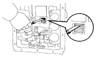
INSPECT INDIVIDUAL PISTON OPERATION
-
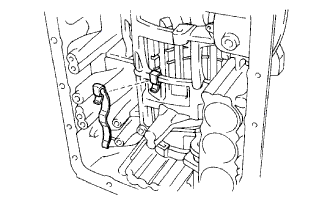
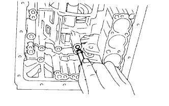
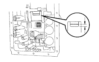
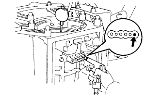
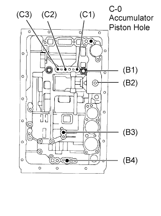
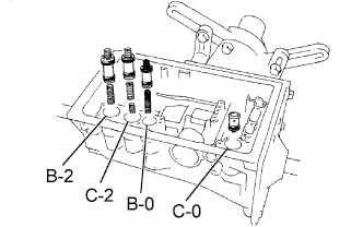
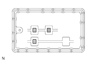
Check the operating sound while applying compressed air into the oil hole indicated in the illustration.
Tech Tips
When inspecting the overdrive direct clutch, check with the C-0 accumulator piston hole closed.
If there is no sound, disassemble and check the parts installation condition.
-
Overdrive direct clutch (C1)
-
Direct clutch (C2)
-
Forward clutch (C3)
-
Overdrive brake (B1)
-
2nd coast brake (B2)
-
2nd brake (B3)
-
1st and reverse brake (B4)
-
-
-
INSTALL MANUAL VALVE LEVER SHAFT OIL SEAL
-
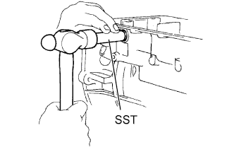
Using SST and a hammer, tap in 2 new oil seals.
- SST
- 09350-30020 ( 09350-07110 )
-
-
INSTALL MANUAL VALVE LEVER SHAFT
-
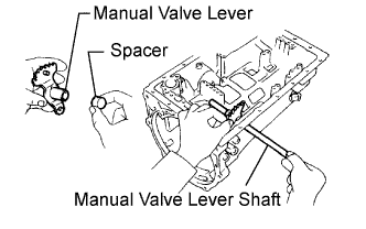
Install a new spacer to the manual valve lever.
-
Install the manual valve lever shaft to the transmission case through the manual valve lever.
-
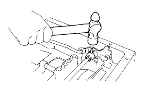
Using a hammer, tap in a new spring pin.
-
Align the manual valve lever indentation with the spacer hole, and stake them with the punch.
-
Make sure that the shaft rotates smoothly.
-
-
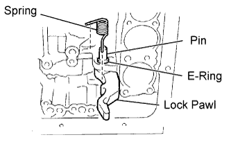
INSTALL PARKING LOCK PAWL SHAFT
-
Install the E-ring to the shaft.
-
Install the parking lock pawl, shaft and spring.
-
-
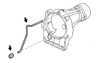
INSTALL PARKING LOCK ROD
-
Connect the parking lock rod to the manual valve lever.
-
-
INSTALL PARKING LOCK PAWL BRACKET
-
Place the parking lock pawl bracket onto the transmission case and install the 3 bolts.
- Torque:
- 7.4 N*m { 75 kgf*cm, 65 in.*lbf }
-
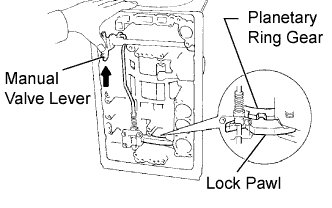
Shift the manual valve lever to the P position, and confirm that the planetary ring gear is correctly locked up by the lock pawl.
-
-
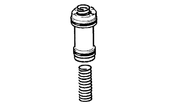
INSTALL C-0 ACCUMULATOR PISTON
-
Coat a new O-ring with ATF, and install it to the piston.
-
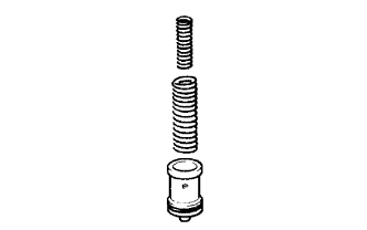
Install the 2 springs and accumulator piston to the hole.
Standard C-0 accumulator spring Inner spring Free Length Outer Diameter Color 51.5 mm (2.028 in.) 14.02 mm (0.552 in.) Red Outer spring Free Length Outer Diameter Color 79.9 mm (3.146 in.) 20.9 mm (0.823 in.) Light Blue
-
-
INSTALL B-0 ACCUMULATOR PISTON
-
Coat 2 new O-rings with ATF, and install them to the piston.
-
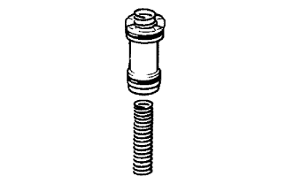
Install the spring and accumulator piston to the hole.
Standard B-0 accumulator spring Free Length Outer Diameter Color 62.0 mm (2.441 in.) 16.0 mm (0.630 in.) Green
-
-
INSTALL C-2 ACCUMULATOR PISTON
-
Coat 2 new O-rings with ATF, and install them to the piston.
-
Install the 2 springs and accumulator piston to the hole.
Standard C-2 accumulator spring Inner spring Free Length Outer Diameter Color 42.1 mm (1.657 in.) 14.7 mm (0.579 in.) Pink Outer spring Free Length Outer Diameter Color 68.53 mm (2.698 in.) 20.2 mm (0.795 in.) Blue
-
-
INSTALL B-2 ACCUMULATOR PISTON
-
Coat 2 new O-rings with ATF, and install them to the piston.
-
Install the spring and accumulator piston to the hole.
Standard B-2 accumulator spring Free Length Outer Diameter Color 70.5 mm (2.776 in.) 19.9 mm (0.784 in.) Light Gray
-
-
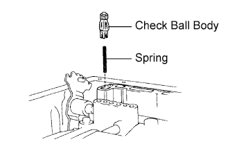
INSTALL CHECK BALL BODY
-
Install the spring and check ball body.
-
-
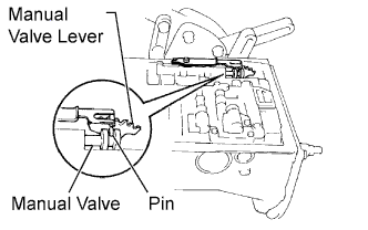
INSTALL TRANSMISSION VALVE BODY ASSEMBLY
-
Align the groove of the manual with the pin of the lever.
-
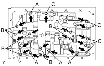
Install the 20 bolts.
- Torque:
- 11 N*m { 112 kgf*cm, 8 ft.*lbf }
Tech Tips
Each bolt length is indicated below.
Bolt length:
23 mm (0.91 in.) for A
28 mm (1.10 in.) for B
36 mm (1.42 in.) for C
-
-
INSTALL TRANSMISSION WIRE
-
Coat a new O-ring with ATF, and install it to the transmission wire.
-
Install the transmission wire to the case, and install the stopper plate with the bolt.
- Torque:
- 5.4 N*m { 55 kgf*cm, 48 in.*lbf }
-
Connect the connectors to the shift solenoid valves.
-
-
INSTALL VALVE BODY OIL STRAINER ASSEMBLY
-
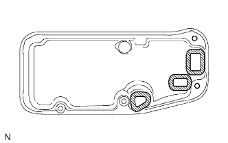
Install 3 new gaskets on the oil strainer.
-
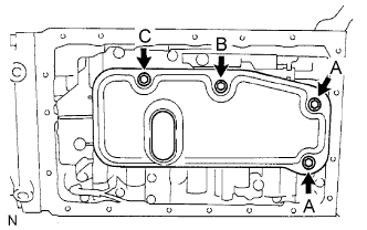
Install the oil strainer with the 4 bolts.
- Torque:
- 10 N*m { 102 kgf*cm, 7 ft.*lbf }
Tech Tips
Each bolt length is indicated below.
Bolt length:
14 mm (0.55 in.) for A
20 mm (0.79 in.) for B
23 mm (0.91 in.) for C
-
-
INSTALL OIL CLEANER MAGNET
-
Install the 3 magnets.
-
-
INSTALL AUTOMATIC TRANSMISSION OIL PAN SUB-ASSEMBLY
-
Remove all old seal packing from the contacting surfaces of the transmission case and oil pan.
Note
Be careful not to drop oil on the contacting surfaces of the transmission case and oil pan.
-
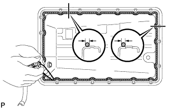
Apply seal packing to the oil pan.
Seal packing Toyota Genuine Seal Packing 1281, Three Bond 1281 or equivalent Seal diameter 2 to 3 mm (0.0788 to 0.118 in.) -
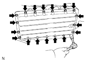
Install the oil pan with the 19 bolts.
- Torque:
- 7.4 N*m { 75 kgf*cm, 65 in.*lbf }
-
-
INSTALL SENSOR ROTOR
-
Using a snap ring expander, install the snap ring.
-
Install the key on the output shaft.
-
Align the groove of the sensor rotor with the key, and install the sensor rotor.
-
-
INSTALL SPEEDOMETER DRIVE GEAR
-
Install the ball to the output shaft.
-
Align the groove of the speedometer drive gear with the ball and install the speedometer drive gear.
-
Using a snap ring expander, install the snap ring.
-
-
INSTALL AUTOMATIC TRANSMISSION EXTENSION HOUSING OIL SEAL
-
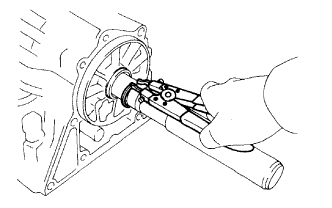
Using SST and a hammer, tap in a new oil seal.
- SST
- 09950-60010 ( 09951-00580 )
- 09950-70010 ( 09951-07100 )
Standard oil seal depth 5.8 to 6.2 mm)0.228 to 0.244 in.) Note
Be careful not to damage the oil seal lip.
-
Coat the lip of a new oil seal with MP grease.
-
-
INSTALL EXTENSION HOUSING DUST DEFLECTOR
-
Using a screwdriver and hammer, tap in a new dust deflector.
-
-
INSTALL EXTENSION HOUSING BUSH APPLY TUBE
-
INSTALL EXTENSION HOUSING BUSH APPLY TUBE GASKET
-
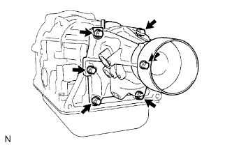
INSTALL EXTENSION HOUSING SUB-ASSEMBLY
-
Apply seal packing or equivalent to the 6 bolts.
Adhesive Toyota Genuine Adhesive 1344, Three Bond 1344 or equivalent -
Install a new gasket and the extension housing to the case with the 6 bolts.
- Torque:
- 36 N*m { 370 kgf*cm, 27 ft.*lbf }
Tech Tips
The 2 lower bolts are shorter.
-
-
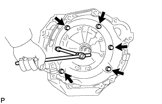
INSTALL AUTOMATIC TRANSMISSION HOUSING
-
Clean the threads of the bolts and case with non-residue solvent.
-
Apply adhesive or equivalent to the 6 bolts.
Adhesive Toyota Genuine Adhesive 1344, Three Bond 1344 or equivalent -
Install the transmission housing with the 6 bolts.
- Torque:
- 34 N*m { 347 kgf*cm, 25 ft.*lbf, for 14 mm bolt }
- 57 N*m { 581 kgf*cm, 42 ft.*lbf, for 17 mm bolt }
-
-
INSTALL SPEED SENSOR (SP2)
-
Install a new O-ring to the sensor.
-
Install the sensor with the bolt.
- Torque:
- 5.4 N*m { 55 kgf*cm, 48 in.*lbf }
-
-
INSTALL SPEEDOMETER SENSOR
-
Install a new O-ring to the sensor.
-
Install the sensor with the bolt.
- Torque:
- 5.4 N*m { 55 kgf*cm, 48 in.*lbf }
-
-
INSTALL SPEED SENSOR (NC0)
-
Install a new O-ring to the sensor.
-
Install the speed sensor with the bolt.
- Torque:
- 5.4 N*m { 55 kgf*cm, 48 in.*lbf }
-
-
INSTALL OIL COOLER TUBE UNION
-
Coat 2 new O-rings with ATF, and install them to each tube union.
-
Install the 2 tube unions.
- Torque:
- 29 N*m { 300 kgf*cm, 22 ft.*lbf }
-
-
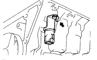
INSTALL ATF TEMPERATURE SENSOR
-
Install the bolt with the wire harness bracket.
- Torque:
- 5.4 N*m { 55 kgf*cm, 48 in.*lbf }
-
Coat a new O-ring with ATF and install it to the sensor.
-
Using a 19 mm union nut wrench, install the ATF temperature sensor.
- Torque:
- 29 N*m { 300 kgf*cm, 22 ft.*lbf }
Note
Use the formula to calculate special torque values for situations where a union nut wrench is combined with a torque wrench Click here.
-
Connect the ATF temperature sensor clamp to the wire harness bracket.
-
-
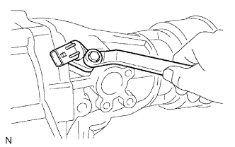
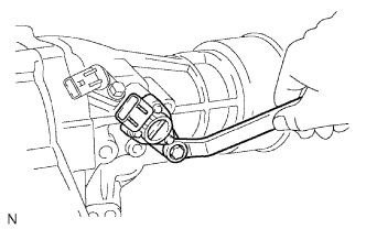
INSTALL PARK/NEUTRAL POSITION SWITCH ASSEMBLY
Tech Tips
Make sure that the manual valve lever shaft has not been rotated prior to installing the park/neutral position switch as the detent spring may become detached from the manual valve lever shaft.
-
Install the park/neutral position switch onto the manual valve lever shaft, and temporarily install the adjusting bolt.
-
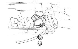
Install a new lock washer. Install and torque the nut.
- Torque:
- 7.0 N*m { 71 kgf*cm, 62 in.*lbf }
-
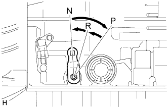
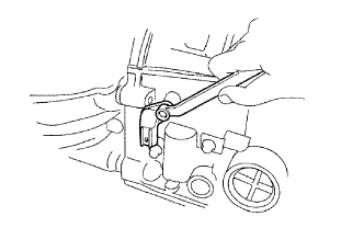
Push the control shaft rearward as much as possible.
-
Return the control shaft lever 2 notches to the N position.
-
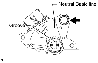
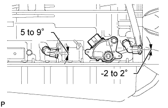
Align the neutral basic line with the switch groove as shown in the illustration, and tighten the adjusting bolt.
- Torque:
- 13 N*m { 130 kgf*cm, 9 ft.*lbf }
Tech Tips
Bend at least 2 of the lock washer tabs.
-
-
INSTALL TRANSMISSION CONTROL SHAFT LEVER LH
-
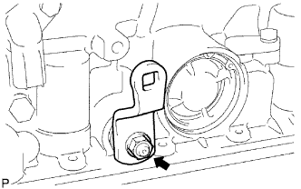
Install the control shaft lever with the washer and nut.
- Torque:
- 16 N*m { 160 kgf*cm, 12 ft.*lbf }
-
-
INSTALL BREATHER HOSE
-
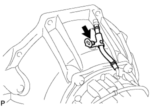
Install the breather hose with the bolt.
- Torque:
- 7.4 N*m { 75 kgf*cm, 65 in.*lbf }
-
-
INSTALL DRAIN PLUG
-
Install a new gasket and the drain plug.
- Torque:
- 20 N*m { 205 kgf*cm, 15 ft.*lbf }
-