REPAIR INSTRUCTION INITIALIZATION
Note
When disconnecting the cable from the negative (-) battery terminal, initialize the following system(s) after the cable is reconnected.
-
Initialization procedures are below the table.
System Name Meter / Gauge System Power Window Control System (w/ Jam Protection Function)
-
INITIALIZATION RELATED TO A750F AUTOMATIC TRANSMISSION SYSTEM
-
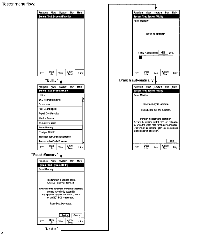
RESET MEMORY
Note
-
Perform the RESET MEMORY procedures (A/T initialization) when replacing the automatic transmission assembly, engine assembly or ECM.
-
The RESET MEMORY can be performed only with the intelligent tester.
Tech Tips
The ECM memorizes the vehicle conditions when the ECT controls the automatic transmission assembly and engine assembly. Therefore, when the automatic transmission assembly, engine assembly, or ECM has been replaced, it is necessary to reset the memory so that the ECM can memorize the new information.
The reset procedures are as follows.
-
Turn the ignition switch OFF.
-
Connect the intelligent tester to the DLC3.
-
Turn the ignition switch ON and push the intelligent tester main switch ON.
-
Perform the reset memory procedure from the main menu.
CAUTION:
After performing the RESET MEMORY procedures, be sure to perform the Road Test Click here as described earlier.
Tech Tips
The ECM learns through the Road Test.
-
-
-
INITIALIZATION RELATED TO LIGHTING SYSTEM
-
HEIGHT CONTROL SENSOR SIGNAL INITIALIZATION (for HID Headlight)
Note
-
Initialize the height control sensor signal after the vehicle height changes due to replacement of the suspension or after performing such operations as removal and reinstallation or replacement of the rear height control sensor sub-assembly.
-
Initialization is also necessary when the headlight leveling ECU is replaced.
-
Adjust the headlight aim after initializing the headlight leveling ECU Click here.
-
When a malfunction is detected in the automatic headlight beam level control system, the height control sensor signal initialization is impossible. Perform troubleshooting before initialization.
-
PREPARE VEHICLE FOR INITIALIZATION (Procedure A)
-
Unload the trunk and vehicle, and make sure that the spare tire, tools and jack are in their original positions.
-
Check that there are no occupants in the vehicle.
-
Turn off the headlights.
-
Stop the vehicle on a level surface and keep the vehicle height unchanged.
-
Go to procedure B.
-
-
CHECK WARNING LIGHT (Procedure B)
-
Turn the ignition switch to ON and check the headlight beam level control system warning light.
OK Condition Specified Condition The headlight leveling ECU is replaced with a new one. Warning light continuously blinks 6 times at 2 Hz. Removal and reinstallation of the headlight leveling ECU, replacement of the rear height control sensor, removal and reinstallation of the rear height control sensor, replacement of the suspension, etc. Warning light comes on for approximately 3 seconds, and then turns off (bulb check function). Tech Tips
If the warning light does not come on when turning the ignition switch to ON, perform inspections and repairs according to "Problem Symptoms Table" Click here.
Result Result Proceed to OK Procedure C NG See procedure Click here
-
-
INITIALIZATION (Procedure C)
- SST
- 09843-18040
-
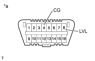
Text in Illustration *a Front view of DLC3 Connect terminals 4 (CG) and 8 (LVL) of the DLC3 using SST.
-
Turn the low beam headlights on and off using the light control switch within 20 seconds after connecting the terminals.
Tech Tips
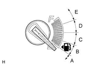
The number of times the low beam headlights need to be turned on and off is determined by the present fuel level as shown below.
Fuel Level Number of Times to Turn Low Beam Headlights on and off Fuel level is within range A. 1 Fuel level is within range B. 2 Fuel level is within range C. 3 Fuel level is within range D. 4 Fuel level is within range E. 5 Note
-
Turn the low beam headlights on and off at approximately 3-second intervals.
-
Be sure to operate the headlight dimmer switch from the outside of the vehicle.
-
-
Check the warning light.
OK Condition Specified Condition The headlight leveling ECU is replaced with a new one. Blinks 6 times at 2 Hz → Blinks N* times at 2 Hz, and then turns off. Removal and reinstallation of the headlight leveling ECU, replacement of the rear height control sensor, removal and reinstallation of the rear height control sensor, replacement of the suspension, etc. Off → Blinks N* times at 2 Hz, and then turns off. Tech Tips
-
*: The number of times that the indicator blinks is determined by the number of times the low beam headlights are turned on and off.
-
If the calculated vehicle height is not within the acceptable range, the rear height control sensor initialization will end as an abnormal termination, and the warning indicator will blink 6 times at 2 Hz continuously. Disconnect SST from the DLC3 and turn the ignition switch off. Then restart from "Check Warning Light".
-
If initialization cannot be finished normally, check the LVL terminal circuit Click here, or perform inspections and repairs according to "Problem Symptoms Table" Click here.
Result Result Proceed to OK END NG See procedure Click here
-
-
-
-
REGISTRATION RELATED TO WIRELESS DOOR LOCK CONTROL SYSTEM (for Built-in Type Door Control Receiver)
-
DESCRIPTION OF CODE REGISTRATION
Tech Tips
-
Recognition code registration is necessary when replacing the door control transmitter or the door control receiver.
-
Add mode is used to register new recognition codes while retaining codes already registered. This mode is used when a new transmitter is added. If the number of registered codes exceeds 4, the previously registered codes will be erased in order, starting from the first registered code.
-
Rewrite mode is used to erase all previously registered recognition codes in order to register new recognition codes. This mode is used when the transmitter or the receiver is replaced.
-
Synchronization mode is used to renew the sequential code (rolling code) of the transmitter and synchronize it with the registered recognition code. This mode is used when the transmitter does not function because they are unsynchronized. Up to 4 transmitters can be synchronized at once (If a transmitter's switch is pressed while out of range of the theft warning ECU, the system will not be able to synchronize the sequential code (rolling code) with the registered recognition code. At this time, the system will automatically synchronize them. However, automatic synchronization can be performed only 500 times. Therefore, it its necessary to use this mode after they have synchronized 500 times).
-
Erase mode is used to erase all the registered codes and disable the wireless door lock function. This mode is used when the transmitter is lost.
-
All of the following registration procedures must be performed in order.
-
-
REGISTER RECOGNITION CODE
-
Check that the following condition is met.
No key in the ignition key cylinder.
-
Insert the key into the ignition key cylinder.
-
Wait for the 5 seconds.
Tech Tips
If the key is pulled out from the ignition key cylinder or the ignition switch is turned ON, the registration mode will be canceled.
-
Turn the ignition switch from OFF to ON 5 times within 10 seconds to turn on the security indicator light.
Tech Tips
If the key is pulled out from the ignition key cylinder, the registration mode will be canceled.
-
Open and close the driver side door once and turn the ignition switch from ON to OFF within 30 seconds.
Tech Tips
If the key is pulled out from the ignition key cylinder or the driver side door is opened and closed twice or more, the registration mode will be canceled.
-
Check the response to registration mode.
-
Perform the following operations (mode selection) within 30 seconds.
-
Perform the driver side door open-close operation according to the details below. Then turn the ignition switch ON and OFF.
Number of open-close operations of the driver side door:
-
Add mode
Open-close operation: Once
-
Rewrite mode:
Open-close operation: Twice
-
Synchronization mode:
Open-close operation: 3 times
-
Erase mode:
Open-close operation: 4 times
Tech Tips
If any of the following operations are performed, the registration mode will be canceled.
-
The key is removed from the ignition key cylinder.
-
The driver side door is opened and closed 5 times or more.
-
The ignition switch is turned ON before opening the driver side door.
-
-
Check the response to the selected mode.
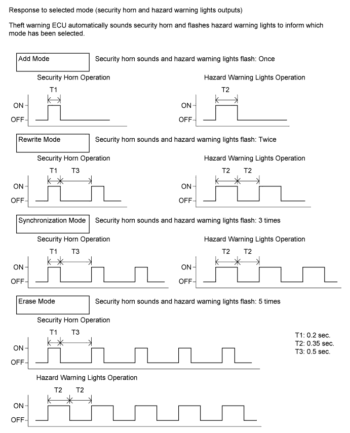
Tech Tips
If erase mode is selected, the registration procedures are completed.
-
Press the LOCK and UNLOCK switches on the transmitter simultaneously.
-
Press a single switch (LOCK or UNLOCK).
-
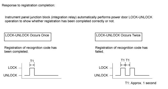
After completing the above step, check the response to the registration completion within 3 seconds.
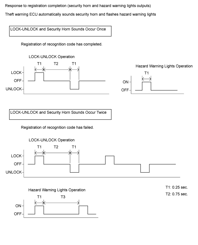
Tech Tips
-
If LOCK-UNLOCK operation and the security horn sounds occur twice, the registration of the recognition code has failed. Perform the registration procedures again from the beginning.
-
If registering another transmitter, repeat the procedures after the response to the selected mode confirmation. All 4 recognition codes can be registered consecutively.
-
-
Perform either of the following.
-
Open the door.
-
Insert the key into the ignition key cylinder.
-
Turn the ignition switch ON.
-
-
Registration of the recognition codes (add mode and rewrite mode) is completed.
-
-
-
WIRELESS DOOR LOCK CONTROL SYSTEM (for Non-built-in Type Door Control Receiver)
-
DESCRIPTION OF CODE REGISTRATION
Tech Tips
-
Recognition code registration is necessary when replacing the door control transmitter or the door control receiver.
-
Add mode is used to register new recognition codes while retaining codes already registered. This mode is used when a new transmitter is added. If the number of registered codes exceeds 4, the previously registered codes will be erased in order, starting from the first registered code.
-
Rewrite mode is used to erase all previously registered recognition codes in order to register new recognition codes. This mode is used when the transmitter or the receiver is replaced.
-
Confirmation mode is used to confirm how many recognition codes have already been registered before another recognition code is registered.
-
Prohibition mode is used to erase all the registered codes and disable the wireless door lock function. This mode is used when the transmitter is lost.
-
All of the following registration procedures must be performed in order.
-
-
REGISTER RECOGNITION CODE
-
Check that the following conditions are met.
-
No key in the ignition key cylinder.
-
The driver side door is opened (the other doors are closed).
-
-
Insert the key into the ignition key cylinder, then pull it out twice within 5 seconds.
-
Perform the following operations within 40 seconds.
-
Close and open the driver side door twice.
-
Insert the key into the ignition key cylinder, then pull it out.
-
-
Perform the following operations within 40 seconds.
-
Close and open the driver side door twice.
-
Insert the key into the ignition key cylinder and close the driver side door.
-
-
Perform the following operations within 40 seconds.
-
Operate the ignition switch according to the number of times shown below.
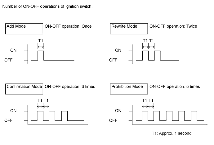
Tech Tips
If the number of ignition switch ON-OFF operations is 0, 4, 6, or more, there will be no response (power door lock and unlock operation) to show which mode has been selected.
-
Remove the key from the ignition key cylinder.
-
-
Check the response to the selected mode within 3 seconds.
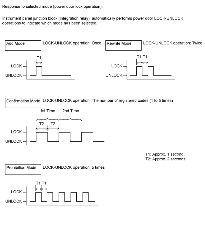
Tech Tips
-
In the confirmation mode, LOCK-UNLOCK operation will occur once for each recognition code that has been registered. For example, if 2 recognition codes have been registered, the LOCK-UNLOCK operation will occur 2 times.
-
In confirmation mode, if no recognition codes have been registered, the LOCK-UNLOCK operation will occur 5 times.
-
If confirmation mode or prohibition mode is selected, the operation ends after the response to the selected mode completes.
-
-
Within 40 seconds of completing the confirmation mode operation, press the LOCK and UNLOCK switches on the transmitter simultaneously.
-
After completing the above step, press a single switch (LOCK or UNLOCK) within 5 seconds.
-
After completing the above step, check the response to the registration completion within 3 seconds.
Tech Tips
-
If the registration of the recognition code has failed, perform the registration procedures from the beginning.
-
If registering another transmitter, repeat the procedures after the response to the selected mode confirmation. All 4 recognition codes can be registered consecutively.
-
-
Perform either of the following.
-
Open the door.
-
Insert the key into the ignition key cylinder.
-
-
Registration of the recognition codes (add mode and rewrite mode) is completed.
-
-
-
CALIBRATION RELATED TO METER / GAUGE SYSTEM
-
DESCRIPTION
Note
Do not place magnetic or metal objects on or near the accessory meter.
Tech Tips
The procedures described below are for vehicles equipped with an accessory meter (multi-display).
-
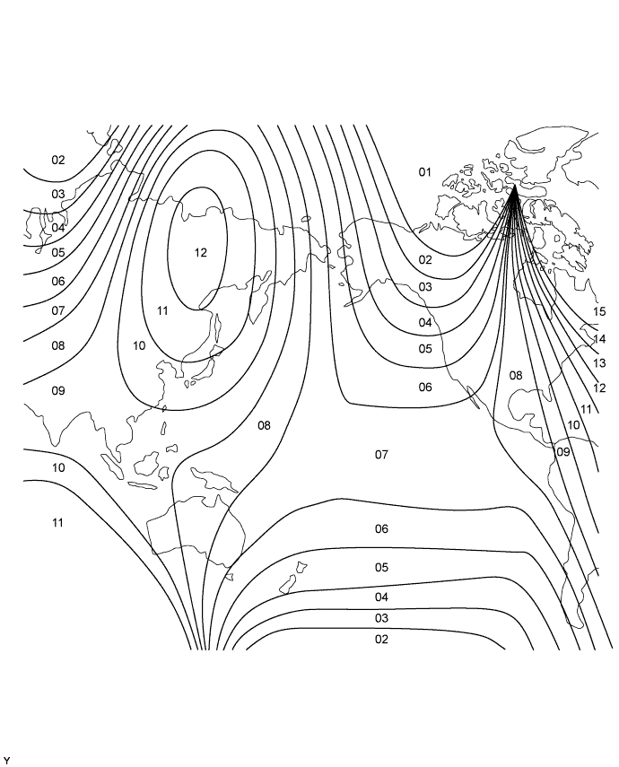
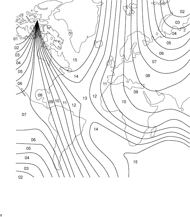
The location of magnetic north differs depending on the vehicle location. Adjustment of the compass' magnetism is required to correct possible compass deviations from true north.
-
Compass function calibration is necessary when: 1) purchasing a vehicle; 2) disconnecting and reconnecting the cable of the negative (-) battery terminal; 3) replacing the vehicle battery; 4) driving the vehicle out of the set zone (see the zone map below); or 5) placing magnetic or metal objects near the accessory meter (the direction indication on the display blinks).
-
-
PERFORM CALIBRATION
CAUTION:
-
Strictly observe posted speed limits, traffic laws and road conditions.
-
Make sure no people are near the vehicle.
Note
-
Perform the circling calibration in a spacious area that does not have artificial magnetic influence. Calibration cannot be performed in underground parking lots, areas under a steel tower and areas between tall buildings.
-
When performing calibration, do not operate the air conditioner, power windows, or any other electrical system.
-
A compass may become magnetized during shipping by vessels or freight cars. Make sure to perform calibration and ensure that the calibration described below is performed properly. If calibration cannot be completed despite driving the vehicle in a circle several times, the vehicle's magnetic field may be interfering with the calibration. Demagnetize the vehicle using a demagnetizer and perform calibration again.
-
Circling calibration
-
Select compass mode.
-
Press and hold INFO for 3 seconds to enter the compass correction mode.
-
Press RESET.
-
Drive the vehicle slowly in a full circle within 128 seconds.
Tech Tips
-
If the circling calibration is completed, the correct direction is displayed automatically.
-
If the correct direction is not displayed after driving the vehicle as specified, change the vehicle location.
-
-
If enough space is not available to drive in a circle, perform the following:
-
Drive the vehicle forward with the steering wheel fully turned to the right, and then drive in reverse with the steering wheel fully turned to the left.
-
Repeat the pattern above 2 times within 128 seconds.
Tech Tips
-
If the circling calibration is completed, the correct direction is displayed automatically.
-
If the correct direction is not displayed after driving the vehicle as specified, change the vehicle location.
-
-
-
Compass correction mode cancellation
-
Press RESET after performing the circling calibration.
-
Press INFO or wait for 6 seconds to end the compass correction mode.
-
-
Zone setting
-
Select compass mode.
-
Press and hold INFO for 3 seconds to enter compass correction mode.
-
Press H to select a higher zone number. Press M to select a lower zone number.
-
Press INFO or wait for 6 seconds to end compass correction mode.
-
-
-
-
INITIALIZATION RELATED TO POWER WINDOW CONTROL SYSTEM (w/ Jam Protection Function)
-
RESET (INITIALIZE) POWER WINDOW REGULATOR MOTOR ASSEMBLY (for Driver Side)
Note
Resetting the power window regulator motor assembly (initializing the pulse sensor) is necessary if one of the following occurs: 1) the battery cable is disconnected; 2) the power window regulator master switch assembly, wire harness, power window regulator switch assembly, power window regulator or power window regulator motor assembly is replaced or removed / installed; or 3) the IG1 H-fuse, PWR H-fuse, DOOR fuse, ECU-IG&GAUGE fuse or IG1 relay is replaced. If resetting is not performed, the power window regulator master switch assembly will not be able to operate the auto up/down function and jam protection function.
-
Turn the ignition switch ON.
-
Open the power window halfway by pressing the power window regulator master switch assembly.
-
Fully pull up on the switch until the power window is fully closed and continue to hold the switch for at least 1 second.
If the auto up/down function operates normally, reset operations are completed. If abnormal, follow the 3 steps below.
-
Check that the auto up/down function operates normally.
-
Disconnect the cable from the negative (-) battery terminal for 10 seconds.
-
Connect the cable to the negative (-) battery terminal.
-
Perform the first 4 steps again.
If the auto up/down function operates normally, reset operations have been completed at this time. If abnormal, follow the 4 steps below.
-
Turn the ignition switch ON.
-
Open the power window halfway by pressing the power window regulator master switch assembly.
-
Fully pull up on the switch until the power window is fully closed and continue to hold the switch for approximately 12 seconds after the power window is fully closed.
-
Check that the auto up/down function operates normally.
-
-