GENERATOR DISASSEMBLY

-
REMOVE GENERATOR PULLEY
-
Mount the generator in a vise between aluminum plates.
-
Install SST 1-A to the pulley shaft.
- SST
- 09820-63011 ( 09820-06010, 09820-06021 )
Tech Tips
SST 1-A and B 09820-06010 SST 2 09820-06021 -
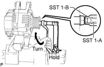
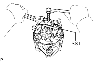
Install SST 1-B to SST 1-A.
-
Hold SST 1-A with a torque wrench and turn SST 1-B clockwise with the specified torque.
- Torque:
- 39 N*m { 400 kgf*cm, 29 ft.*lbf }
Note
Check that SST is secured to the rotor shaft.
-
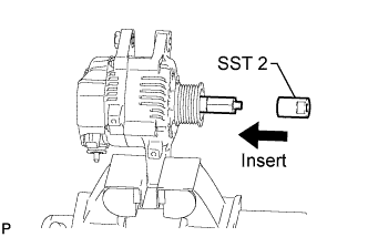
Insert SST 2 and attach it to the pulley nut.
-
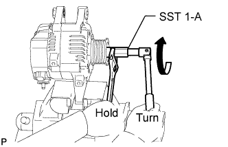
To loosen the pulley nut, turn SST 1-A in the direction shown in the illustration.
Note
To prevent damage to the rotor shaft, do not loosen the pulley nut more than one-half of a turn.
-
Remove SST 2 from the generator.
-
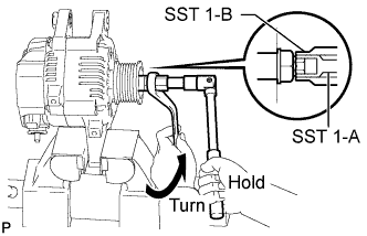
Turn SST 1-B in the direction shown in the illustration and remove SST 1-A and B.
-
Remove the pulley nut and pulley.
-
-
REMOVE GENERATOR REAR END COVER
-
Remove the nut and terminal insulator.
-
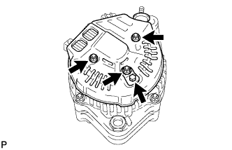
Remove the bolt, 3 nuts, plate terminal and end cover.
-
-
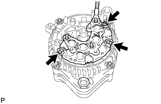
REMOVE GENERATOR BRUSH HOLDER ASSEMBLY
-
Remove the brush holder cover from the brush holder.
-
Remove the 2 screws and brush holder.
-
-
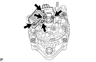
REMOVE VOLTAGE REGULATOR ASSEMBLY
-
Remove the 3 screws and voltage regulator.
-
-
REMOVE GENERATOR HOLDER WITH RECTIFIER
-
Remove the 3 screws and holder with rectifier.
-
-
REMOVE GENERATOR RECTIFIER END FRAME
-
Remove the 3 rubber insulators.
-
Remove the seal plate.
-
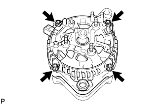
Remove the 4 nuts.
-
Using SST, remove the rectifier end frame.
- SST
- 09286-46011
-
-
REMOVE GENERATOR ROTOR ASSEMBLY
-
Remove the generator washer from the rotor.
-
Remove the rotor from the drive end frame.
Note
Do not drop the rotor.
-