WATER PUMP INSTALLATION

-
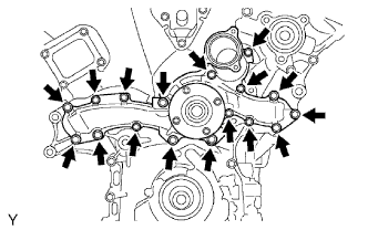
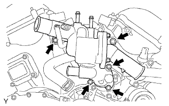
INSTALL WATER PUMP ASSEMBLY
-
Install a new gasket and the water pump with the 17 bolts.
- Torque:
- 9.0 N*m { 92 kgf*cm, 80 in.*lbf, for 10 mm head }
- 23 N*m { 235 kgf*cm, 17 ft.*lbf, for 12 mm head }
-
-
INSTALL V-RIBBED BELT TENSIONER ASSEMBLY
-
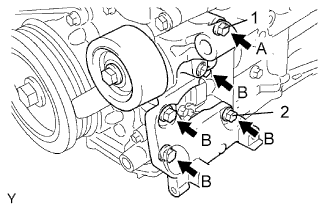
Temporarily install the V-ribbed belt tensioner with the 5 bolts.
-
Install the V-ribbed belt tensioner by tightening bolt 1 and then bolt 2.
- Torque:
- 36 N*m { 367 kgf*cm, 27 ft.*lbf }
-
Tighten the other bolts.
- Torque:
- 36 N*m { 367 kgf*cm, 27 ft.*lbf }
Tech Tips
Each bolt length is as follows:
A = 70 mm (2.76 in.)
B = 33 mm (1.30 in.)
-
-
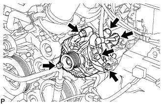
INSTALL GENERATOR ASSEMBLY
-
Install the generator and adjusting bar with the 2 bolts.
- Torque:
- 43 N*m { 438 kgf*cm, 32 ft.*lbf }
-
Install the generator wire with the nut.
- Torque:
- 9.8 N*m { 100 kgf*cm, 87 in.*lbf }
-
Install the terminal cap.
-
Connect the generator connector.
-
-
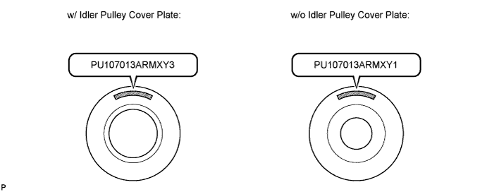
INSTALL NO. 2 IDLER PULLEY
Note
w/o Integrated Type:
The installation of the No. 2 idler pulleys differs depending on the mark on the No. 2 idler pulleys shown in the illustration.
Tech Tips
Use the same procedure for both No. 2 idler pulleys.
-
w/ Idler Pulley Cover Plate (PU107013ARMXY3):
-
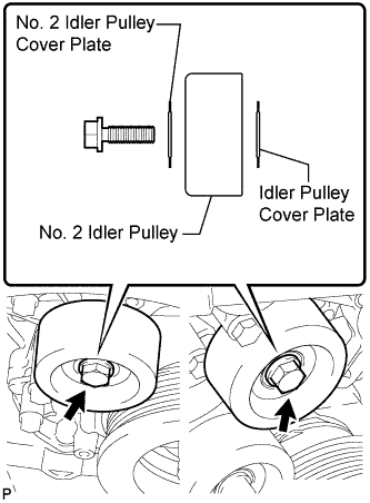
Install the idler pulley cover plate, idler pulley and No. 2 idler pulley cover plate with the bolt.
- Torque:
- 54 N*m { 551 kgf*cm, 40 ft.*lbf }
Note
-
If it is necessary to replace the pulley or either plate, replace the No. 2 idler pulley cover plate, No. 2 idler pulley and idler pulley cover plate as a set with new parts.
-
When replacing parts, make sure to replace the No. 2 idler pulley with a new pulley marked "PU107013ARMXY3".
-
-
w/o Idler Pulley Cover Plate (PU107013ARMXY1):
-
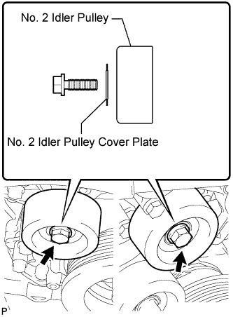
Install the idler pulley and No. 2 idler pulley cover plate with the bolt.
- Torque:
- 54 N*m { 551 kgf*cm, 40 ft.*lbf }
Note
-
If it is necessary to replace the pulley or plate, replace both the pulley and plate with a set of new parts that includes a No. 2 idler pulley cover plate, No. 2 idler pulley and idler pulley cover plate.
-
When replacing parts, make sure to replace the No. 2 idler pulley with a new pulley marked "PU107013ARMXY3".
-
-
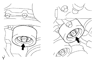
for Integrated Type:
Install the 2 No. 2 idler pulleys with the 2 bolts.
- Torque:
- 54 N*m { 551 kgf*cm, 40 ft.*lbf }
-
-
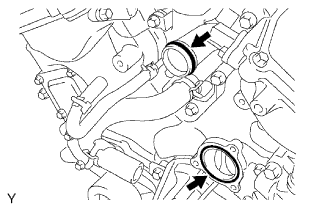
INSTALL WATER INLET HOUSING
-
Install a new O-ring to the water outlet pipe.
-
Install a new O-ring to the water pump.
-
Apply soapy water to the O-ring.
-
Install the water inlet with the 5 bolts.
- Torque:
- 9.0 N*m { 92 kgf*cm, 80 in.*lbf }
-
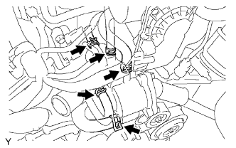
Connect the 3 water by-pass hoses.
-
-
CONNECT RADIATOR HOSE INLET
-
CONNECT RADIATOR HOSE OUTLET
-
INSTALL AIR CLEANER ASSEMBLY
- Torque:
- 8.0 N*m { 82 kgf*cm, 71 in.*lbf }
-
CONNECT NO. 2 VENTILATION HOSE
-
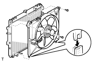
INSTALL FAN SHROUD
-
Install the fan pulley to the water pump.
-
Place the shroud together with the fluid coupling fan between the radiator and engine.
Note
Be careful not to damage the radiator core.
-
Install the coupling fan to the water pump with 4 nuts. Tighten the nuts as much as possible by hand.
-
Attach the shroud's claws to the radiator as shown in illustration.
-
Install the shroud with the 2 bolts.
- Torque:
- 5.0 N*m { 51 kgf*cm, 44 in.*lbf }
-
Connect the reservoir hose to the radiator tank upper.
-
Install the drive belt Click here.
-
Tighten the 4 nuts of the fluid coupling fan.
- Torque:
- 21 N*m { 214 kgf*cm, 15 ft.*lbf }
-
-
CONNECT CABLE TO NEGATIVE BATTERY TERMINAL
-
ADD ENGINE COOLANT
-
Tighten all the plugs and fill the radiator with TOYOTA Super Long Life Coolant (SLLC).
- Torque:
- 13 N*m { 130 kgf*cm, 9 ft.*lbf, for cylinder block drain cock plug }
Standard capacity Item Specified Condition A/T 9.8 liters (10.4 US qts, 8.6 Imp. qts) M/T 8.5 liters (9.0 US qts, 7.5 Imp. qts) Tech Tips
-
TOYOTA vehicles are filled with TOYOTA SLLC at the factory. In order to avoid damage to the engine cooling system and other technical problems, only use TOYOTA SLLC or similar high quality ethylene glycol based non-silicate, non-amine, non-nitrite, non-borate coolant with long-life hybrid organic acid technology (coolant with long-life hybrid organic acid technology consists of a combination of low phosphates and organic acids).
-
Please contact your TOYOTA dealer for further details.
Note
Never use water as a substitute for engine coolant.
-
Fill the radiator reservoir with TOYOTA Super Long Life Coolant (SLLC) to the F line.
-
Install the radiator cap.
-
Bleed air from the cooling system.
-
Warm up the engine until the thermostat opens.
While the thermostat is open, circulate the coolant for several minutes.
-
Maintain the engine speed at 2,500 to 3,000 rpm.
-
Press the inlet and outlet radiator hoses several times by hand to bleed air.
CAUTION:
When pressing the radiator hoses:
-
Wear protective gloves.
-
Be careful as the radiator hoses are hot.
-
Keep your hands away from the radiator fan.
-
-
-
Stop the engine and wait until the coolant cools down to ambient temperature.
CAUTION:
Do not remove the radiator cap while the engine and radiator are still hot. Pressurized, hot engine coolant and steam may be released and cause serious burns.
-
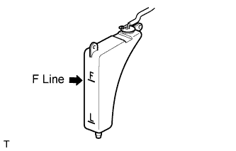
Check the coolant level in the radiator reservoir.
If the coolant level is below the L line, add SLLC to the reservoir F line.
-
-
CHECK FOR ENGINE COOLANT LEAKS
-
Check for engine coolant leaks Click here.
-
-
INSTALL V-BANK COVER
-
Install the cover with the 2 nuts.
- Torque:
- 7.5 N*m { 76 kgf*cm, 66 in.*lbf }
-
-
INSTALL NO. 1 ENGINE UNDER COVER
-
Install the under cover with the 4 bolts.
- Torque:
- 28 N*m { 286 kgf*cm, 21 ft.*lbf }
-
-
PERFORM INITIALIZATION
-
Perform initialization Click here.
Note
Certain systems need to be initialized after disconnecting and reconnecting the cable from the negative (-) battery terminal.
-