FUEL TANK INSTALLATION

-
INSTALL FUEL TANK TO FILLER PIPE HOSE
-
Install the fuel tank to filler pipe hose to the fuel tank.
-
-
INSTALL FUEL TANK BREATHER HOSE
-
Install the fuel tank breather hose to the fuel tank.
-
-
INSTALL FUEL SUCTION WITH PUMP AND GAUGE TUBE ASSEMBLY
-
Apply a light coat of gasoline or grease to a new gasket, and install it to the fuel tank.
-
Install the fuel suction with pump and gauge tube to the fuel tank.
Note
Be careful not to bend the arm of the fuel sender gauge.
-
-
INSTALL FUEL PUMP GAUGE RETAINER
-
Set the fuel pump gauge retainer on the fuel tank. While holding the fuel suction with pump and gauge tube, tighten the retainer one complete turn by hand.
-
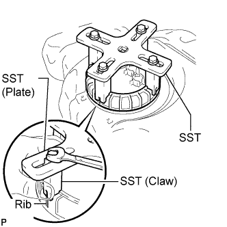
Temporarily install SST (plate and 4 claws) to the fuel pump gauge retainer.
- SST
- 09808-14030
Tech Tips
-
Be sure to use 4 SST (claws) as shown in the illustration.
-
Engage SST (claws) securely with the fuel pump gauge retainer ribs to secure SST.
-
While pressing SST (claws) against the fuel pump gauge retainer ribs securely, install the 4 bolts.
Tech Tips
Install SST while pressing SST (claws) against the fuel pump gauge retainer (toward the center of SST).
-
Install SST (handle).
-
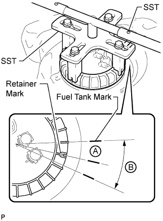
Using SST, tighten the retainer until the mark on the retainer aligns with mark A on the fuel tank as shown in the illustration.
- SST
- 09808-14030
Note
-
Do not use any tools other than those specified in this operation. Damage to the fuel pump gauge retainer or fuel tank may result.
-
Do not press down on SST excessively as this may make the fuel pump gauge retainer hard to rotate, and may damage components.
-
Make sure to rotate SST (handle) horizontally. If SST (handle) is rotated at an angle, SST may come off.
-
Do not spin SST too fast or use an impact wrench as this may result in damage to components.
-
If SST comes off of the fuel pump gauge retainer, loosen SST (bolts) and reinstall SST.
Tech Tips
-
If the alignment is difficult, make sure the mark on the retainer is within range B on the fuel tank.
-
Lightly press down on SST to prevent it from separating from the fuel pump gauge retainer. While pressing SST, rotate the handle slowly to tighten the fuel pump gauge retainer.
-
The tips of SST (claws) can be fitted onto the ribs of the fuel pump gauge retainer.
-
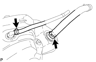
Install the fuel tank return tube and fuel tank main tube to the fuel tank.
-
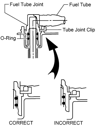
Install the 2 fuel tank tubes with the 2 tube joint clips.
Note
-
-
Check that there are no scratches or foreign objects on the connecting parts.
-
Check that the fuel tube joints are inserted securely.
-
Check that the tube joint clips are on the collars of the fuel tube joints.
-
After installing the tube joint clips, check that the fuel tube joints cannot be pulled off.
-
-
-
INSTALL NO. 1 FUEL EVAPORATION TUBE SUB-ASSEMBLY
-
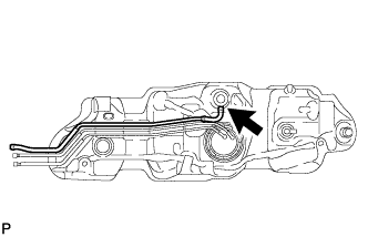
Install the No. 1 fuel evaporation tube.
-
-
INSTALL FUEL TANK CUSHION
-
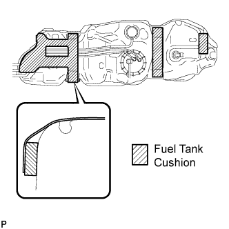
Install 4 new fuel tank cushions.
-
-
INSTALL NO. 1 FUEL TANK PROTECTOR SUB-ASSEMBLY
-
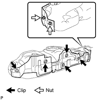
Install the No. 1 fuel tank protector with the 5 clips and 2 nuts.
- Torque:
- 6.0 N*m { 61 kgf*cm, 53 in.*lbf }
-
-
INSTALL FUEL TANK ASSEMBLY
-
Set the fuel tank on a transmission jack and raise the fuel tank.
Note
Do not allow the fuel tank to contact the vehicle, especially the differential.
-
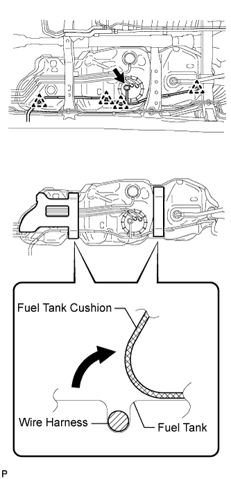
Fold back the 2 cushions.
-
Attach the wire harness to the 4 clamps and connect the fuel pump and sender gauge connector.
Note
Be careful not to cut the wiring.
-
Install the 3 fuel tank bands with the 3 pins and 3 clips.
-
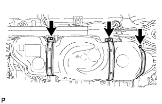
Connect the 3 fuel tank bands with the 3 bolts.
- Torque:
- 61 N*m { 622 kgf*cm, 45 ft.*lbf }
-
-
INSTALL FUEL TANK FILLER PIPE
-
Install the filler pipe with the bolt and nut.
- Torque:
- 19 N*m { 194 kgf*cm, 14 ft.*lbf }
-
-
CONNECT FUEL TANK TO FILLER PIPE HOSE
-
Connect the fuel tank to filler pipe hose to the fuel tank filler pipe.
-
-
CONNECT FUEL TANK BREATHER HOSE
-
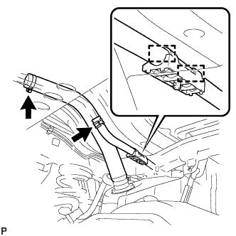
Attach the breather hose to the 2 clamps.
-
Connect the fuel tank breather hose to the fuel tank filler pipe.
-
-
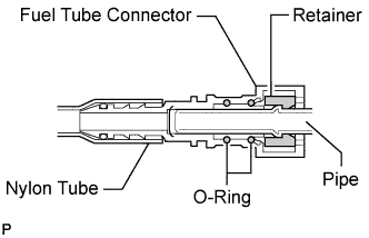
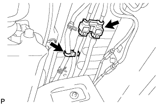
CONNECT FUEL TANK MAIN TUBE SUB-ASSEMBLY AND FUEL TANK RETURN TUBE
Note
Before installing the tube connectors to the pipes, check the connectors for damage and foreign matter.
-
Connect the fuel tank return tube connector to the pipe. Then connect the fuel tank main tube connector to the pipe. Push the 2 tube connectors into the pipe until the tube connector makes a "click" sound.
Note
-
-
Check if there is any damage or foreign objects on the connected part of the fuel pipe.
-
After connecting, check that the pipe and connector are securely connected by pulling them.
-
-
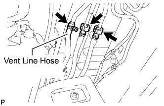
Connect the vent line hose to the fuel pipe.
-
-
INSTALL NO. 3 FUEL TUBE CLAMP
-
Install the 2 tube clamps to the fuel tube.
-
-
INSTALL FUEL TANK PROTECTOR
-
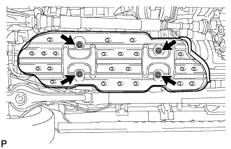
Install the fuel tank protector with the 4 nuts.
- Torque:
- 20 N*m { 204 kgf*cm, 15 ft.*lbf }
-
-
INSTALL FUEL TANK CAP ASSEMBLY
-
CONNECT CABLE TO NEGATIVE BATTERY TERMINAL
Note
When disconnecting the cable, some systems need to be initialized after the cable is reconnected Click here.
-
CHECK FOR FUEL LEAKS
-
Connect the intelligent tester to the DLC3.
-
Turn the ignition switch ON.
Note
Do not start the engine.
-
Push the intelligent tester main switch ON.
-
Select the Active Test and enter the following menus: Powertrain / Engine and ECT / Active Test / Control the Fuel Pump / Speed.
-
-
Check for fuel leaks.
-
Check that there are no fuel leaks after performing maintenance anywhere on the fuel system.
If there are fuel leaks, repair or replace parts as necessary.
-
-