ENGINE UNIT INSPECTION

-
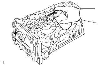
INSPECT OIL NOZZLE
-
Check the oil nozzles for damage or clogging.
If necessary, replace the oil nozzle.
-
-
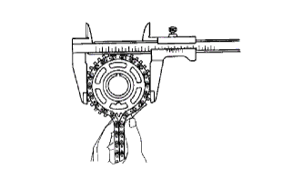
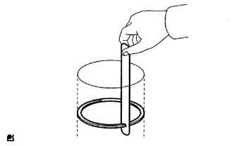
INSPECT CHAIN
-
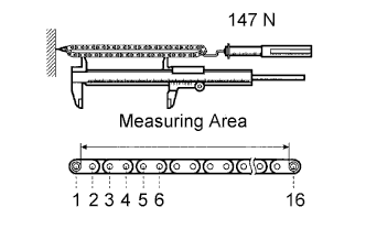
Pull the chain with a force of 147 N (15 kgf, 33 lbf) as shown in the illustration.
-
Using a vernier caliper, measure the length of 16 links.
Maximum chain elongation 147.5 mm (5.807 in.) If the elongation is greater than the maximum, replace the chain.
Note
Make the same measurement pulling at 3 or more places selected at random. Average the measurements.
-
-
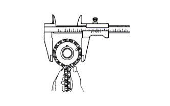
INSPECT NO. 2 CHAIN
-
Pull the chain with a force of 147 N (15 kgf, 33 lbf) as shown in the illustration.
-
Using a vernier caliper, measure the length of 16 links.
Maximum chain elongation 123.6 mm (4.866 in.) If the elongation is greater than the maximum, replace the chain.
Note
Make the same measurement pulling at 3 or more places selected at random. Average the measurements.
-
-
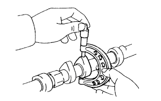
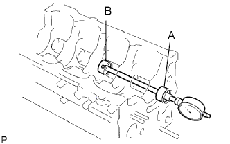
INSPECT CAMSHAFT TIMING GEAR (VVT CONTROLLER)
-
Check the lock of the camshaft timing gear.
-
Clamp the camshaft in a vise, and confirm that the camshaft timing gear is locked.
Note
Be careful not to damage the camshaft.
-
-
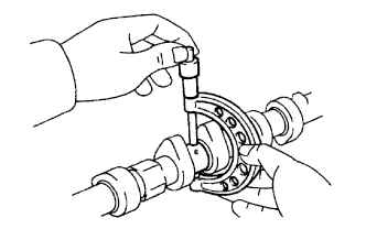
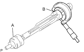
Release the lock pin.
-
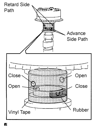
Cover the 4 oil paths of the cam journal with vinyl tape as shown in the illustration.
Tech Tips
2 advance side paths are provided in the groove of the camshaft. Plug one of the paths with a rubber piece.
-
Break through the tape of the advance side path and the retard side path on the opposite side of the groove.
-
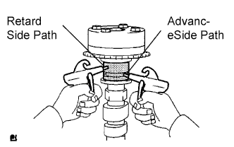
Apply approximately 200 kPa (2.0 kgf/cm2, 28 psi) of air pressure to the paths whose tape was broken in the procedure above.
CAUTION:
Some oil spraying will occur. Contain the spray with a shop rag.
-
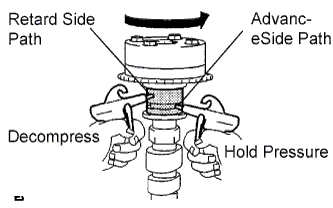
Check that the camshaft timing gear revolves in the advance direction when weakening the air pressure of the retard side path.
OK Gear rotates in advance direction. Tech Tips
This operation releases the lock pin for the extreme retard position.
-
When the camshaft timing gear reaches the extreme advance position, remove the air gun from the retard side path and advance side path, in that order.
Note
Do not remove the air gun from the advance side path first. The gear may abruptly shift in the retard direction and break the lock pin.
-
-
Check for smooth rotation.
-
Rotate the camshaft timing gear within its movable range several times, but do not turn it to the extreme retard position. Check that the gear rotates smoothly.
OK Gear rotates in advance direction. Note
Do not use an air gun to perform the smooth operation check.
-
-
Check the lock in the extreme retard position.
-
Confirm that the camshaft timing gear is locked at the extreme retard position.
-
-
-
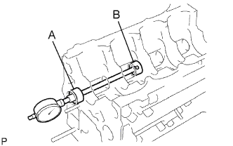
INSPECT NO. 1 CAMSHAFT
-
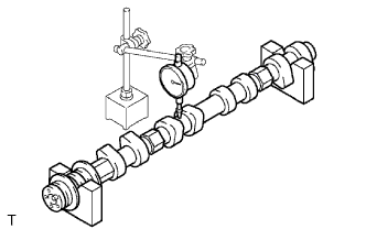
Check the camshaft for runout.
-
Place the camshaft on V-blocks.
-
Using a dial indicator, measure the circle runout at the center journal.
Maximum circle runout 0.03 mm (0.0012 in.) If the circle runout is greater than the maximum, replace the camshaft.
-
-
Using a micrometer, measure the cam lobe height.
Standard cam lobe height 42.855 to 42.955 mm (1.6872 to 1.6911 in.) Minimum cam lobe height 42.855 mm (1.6872 in.) If the cam lobe height is less than the minimum, replace the camshaft.
-
Using a micrometer, measure the journal diameter.
Standard journal diameter Item Specified Condition No. 1 journal 35.949 to 35.965 mm (1.4153 to 1.4159 in.) Other journal 26.959 to 26.975 mm (1.0614 to 1.0620 in.) If the journal diameter is not as specified, check the oil clearance.
-
-
INSPECT NO. 2 CAMSHAFT
-
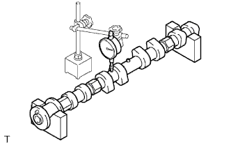
Check the camshaft for runout.
-
Place the camshaft on V-blocks.
-
Using a dial indicator, measure the circle runout at the center journal.
Maximum circle runout 0.03 mm (0.0012 in.) If the circle runout is greater than the maximum, replace the camshaft.
-
-

Using a micrometer, measure the cam lobe height.
Standard cam lobe height 42.854 to 42.954 mm (1.687 to 1.6911 in.) Minimum cam lobe height 42.854 mm (1.6872 in.) If the cam lobe height is less than the minimum, replace the camshaft.
-
Using a micrometer, measure the journal diameter.
Standard journal diameter Item Specified Condition No. 1 journal 35.949 to 35.965 mm (1.4153 to 1.4159 in.) Other journal 26.959 to 26.975 mm (1.0614 to 1.0620 in.) If the journal diameter is not as specified, check the oil clearance.
-
-
INSPECT NO. 1 CHAIN TENSIONER
-
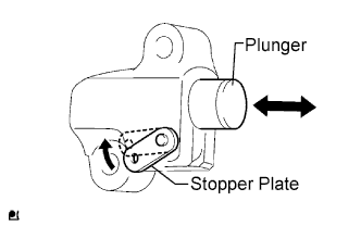
Move the stopper plate upward to release the lock. Push the plunger and check that it moves smoothly.
-
-
INSPECT NO. 2 CHAIN TENSIONER
-
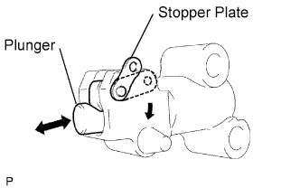
Move the stopper plate downward to release the lock.
Push the plunger and check that it moves smoothly.
-
-
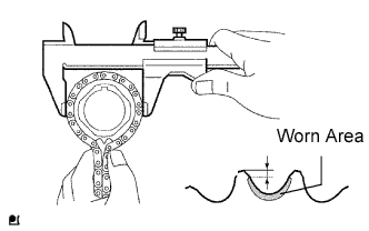
INSPECT CAMSHAFT TIMING SPROCKET
-
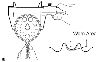
Measure the distance between the most worn out sprocket tip and the beginning of the worn area below the tip.
Minimum distance 1.0 mm (0.039 in.) If the distance is less than the minimum, replace the sprocket.
Tech Tips
If the worn area is too small or difficult to distinguish from a normal area, perform the steps below.
-
Wrap the chain around the sprocket.
-
Using a vernier caliper, measure the sprocket diameter with the chain.
Minimum sprocket diameter (with chain) 113.8 mm (4.480 in.) Tech Tips
The vernier caliper must contact the chain rollers for the measurement.
If the diameter is less than the minimum, replace the chain and sprocket.
-
-
INSPECT CAMSHAFT TIMING GEAR
-
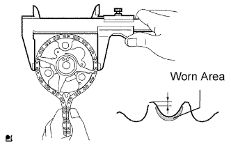
Measure the distance between the most worn out timing gear tip and the beginning of the worn area below the tip.
Minimum distance 1.0 mm (0.039 in.) If the distance is less than the minimum, replace the timing gear.
Tech Tips
If the worn area is too small or difficult to distinguish from a normal area, perform the steps below.
-
Wrap the chain around the timing gear.
-
Using a vernier caliper, measure the sprocket diameter with the chain.
Minimum sprocket diameter (with chain) 113.8 mm (4.480 in.) Tech Tips
The vernier caliper must contact the chain rollers for the measurement.
If the diameter is less than the minimum, replace the chain and timing gear.
-
-
INSPECT CRANKSHAFT TIMING SPROCKET
-
Measure the distance between the most worn out sprocket tip and the beginning of the worn area below the tip.
Minimum distance 1.0 mm (0.039 in.) If the distance is less than the minimum, replace the sprocket.
Tech Tips
If the worn area is too small or difficult to distinguish from a normal area, perform the steps below.
-
Wrap the chain around the drive sprocket.
-
Using a vernier caliper, measure the sprocket diameter with the chain.
Minimum sprocket diameter (with chain) 59.4 mm (2.358 in.) Tech Tips
The vernier caliper must contact the chain rollers for the measurement.
If the diameter is less than the minimum, replace the chain and sprocket.
-
-
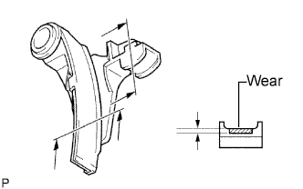
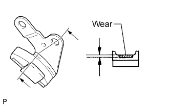
INSPECT CHAIN TENSIONER SLIPPER
-
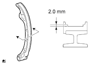
Using a vernier caliper, measure the tensioner slipper wear.
Maximum wear 2.0 mm (0.079 in.) If the wear is greater than the maximum, replace the tensioner slipper.
-
-
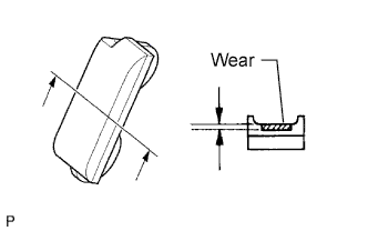
INSPECT CHAIN VIBRATION DAMPER
-
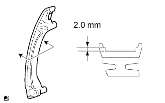
Using a vernier caliper, measure the vibration damper wear.
Maximum wear 2.0 mm (0.079 in.) If the wear is greater than the maximum, replace the vibration damper.
-
-
INSPECT TIMING CHAIN GUIDE
-
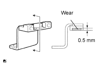
Using a vernier caliper, measure the chain guide wear.
Maximum wear 0.5 mm (0.020 in.) If the wear is greater than the maximum, replace the timing chain guide.
-
-
INSPECT NO. 2 CRANKSHAFT TIMING SPROCKET
-
Wrap the chain around the sprocket.
-
Using a vernier caliper, measure the sprocket diameter with the chain.
Minimum sprocket diameter (with chain) 96.7 mm (3.807 in.) Tech Tips
The vernier caliper must contact the chain rollers for the measurement.
If the diameter is less than the minimum, replace the chain and sprocket.
-
-
INSPECT BALANCE SHAFT DRIVE GEAR
-
Wrap the chain around the sprocket.
-
Using a vernier caliper, measure the sprocket diameter with the chain.
Minimum sprocket diameter (with chain) 75.9 mm (2.988 in.) Tech Tips
The vernier caliper must contact the chain rollers for the measurement.
If the diameter is less than the minimum, replace the chain and sprocket.
-
-
INSPECT NO. 2 CHAIN VIBRATION DAMPER
-
Using a vernier caliper, measure the No. 2 vibration damper wear.
Maximum wear 1.0 mm (0.039 in.) If the wear is greater than the maximum, replace the vibration damper.
-
-
INSPECT NO. 3 CHAIN VIBRATION DAMPER
-
Using a vernier caliper, measure the No. 3 vibration damper wear.
Maximum wear 1.0 mm (0.039 in.) If the wear is greater than the maximum, replace the vibration damper.
-
-
INSPECT NO. 4 CHAIN VIBRATION DAMPER
-
Using a vernier caliper, measure the No. 4 vibration damper wear.
Maximum wear 1.0 mm (0.039 in.) If the wear is greater than the maximum, replace the vibration damper.
-
-
INSPECT CYLINDER HEAD SET BOLT
-
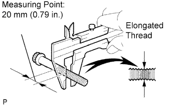
Using a vernier caliper, measure the minimum diameter of the elongated thread at the measuring point.
Standard outside diameter 10.76 to 10.97 mm (0.4236 to 0.4319 in.) Minimum outside diameter 10.40 mm (0.4094 in.) Tech Tips
If a visual check reveals no excessively thin areas, check the center of the bolt (see illustration) and find the area that has the lowest diameter.
If the diameter is less than the minimum, replace the cylinder head bolt.
-
-
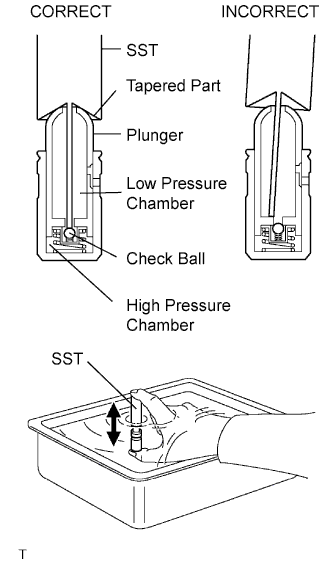
INSPECT VALVE LASH ADJUSTER
Note
-
Keep the lash adjuster free from foreign matter.
-
Only use clean engine oil.
-
Place the lash adjuster into a container full of engine oil.
-
Insert SST's tip into the lash adjuster's plunger and use the tip to press down on the checkball inside the plunger.
- SST
- 09276-75010
-
Squeeze the SST and lash adjuster together to move the plunger up and down 5 to 6 times.
-
Check the movement of the plunger and bleed air.
OK Plunger moves up and down. Note
When bleeding high-pressure air from the compression chamber, make sure that the tip of the SST is actually pressing the checkball as shown in the illustration. If the checkball is not pressed, air will not bleed.
-
After bleeding air, remove SST. Then, try to quickly and firmly press the plunger with a finger.
OK Plunger is difficult to move. If the result is not as specified, replace the lash adjuster.
-
-
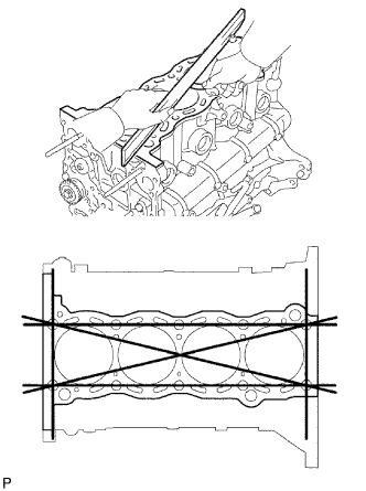
INSPECT CYLINDER HEAD FOR FLATNESS
-
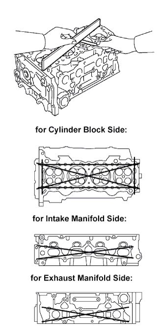
Using a precision straightedge and feeler gauge, measure the surface contacting the cylinder block and manifold for warpage.
Maximum warpage 0.05 mm (0.0020 in.) If the warpage is greater than the maximum, replace the cylinder head.
-
-
INSPECT CYLINDER HEAD FOR CRACKS
-
Using a dye penetrant, check the intake ports, exhaust ports and cylinder surface for cracks.
If cracked, replace the cylinder head.
-
-
INSPECT INTAKE VALVE SEAT
-
Apply a light coat of Prussian blue (or white lead) to the valve face.
-
Lightly press the valve face against the valve seat.
-
Check the valve face and valve seat according to the following procedures.
-
If blue appears 360° around the valve face, the valve face is concentric. If not, replace the valve.
-
If blue appears 360° around the valve seat, the guide and valve face are concentric. If not, resurface the valve seat.
-
Check that the valve seat contact is in the middle of the valve face with the width between 1.0 to 1.4 mm (0.039 to 0.055 in.).
-
-
-
INSPECT EXHAUST VALVE SEAT
-
Apply a light coat of Prussian blue (or white lead) to the valve face.
-
Lightly press the valve face against the valve seat.
-
Check the valve face and valve seat according to the following procedures.
-
If blue appears 360° around the valve face, the valve face is concentric. If not, replace the valve.
-
If blue appears 360° around the valve seat, the guide and valve face are concentric. If not, resurface the valve seat.
-
Check that the valve seat contact is in the middle of the valve face with the width between 1.0 to 1.4 mm (0.039 to 0.055 in.).
-
-
-
INSPECT CAMSHAFT THRUST CLEARANCE
-
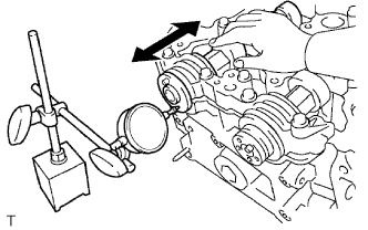
Using a dial indicator, measure the thrust clearance while moving the camshaft back and forth.
Standard thrust clearance 0.10 to 0.24 mm (0.004 to 0.009 in.) Maximum thrust clearance 0.26 mm (0.010 in.) If the thrust clearance is greater than the maximum, replace the cylinder head. If the thrust surface is damaged, replace the camshaft.
-
-
INSPECT CAMSHAFT OIL CLEARANCE
-
Clean the bearing caps and camshaft journals.
-
Place the camshafts on the cylinder head.
-
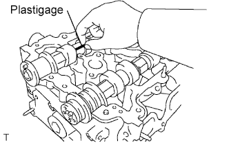
Lay a strip of Plastigage across each of the camshaft journals.
-
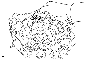
Install the bearing caps Click here.
Note
Do not turn the camshaft.
-
Remove the bearing caps.
-
Measure the Plastigage at its widest point.
Standard oil clearance Item Specified Condition No. 1 journal 0.035 to 0.072 mm
(0.0014 to 0.0029 in.)
Other journal 0.025 to 0.062 mm
(0.0010 to 0.0028 in.)
Maximum oil clearance 0.08 mm (0.0031 in.) If the oil clearance is greater than the maximum, replace the camshaft. If necessary, replace the cylinder head.
-
Completely remove the Plastigage.
-
-
INSPECT COMPRESSION SPRING
-
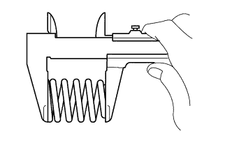
Using a vernier caliper, measure the free length of the inner compression spring.
Standard free length 52.13 mm (2.05 in.) If the free length is not as specified, replace the spring.
-
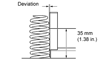
Using a steel square, measure the deviation of the inner compression spring at the position shown in the illustration.
Maximum deviation 1.3 mm (0.0512 in.) Maximum angle (reference) 2° If the deviation is greater than the maximum, replace the spring.
-
-
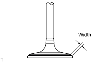
INSPECT INTAKE VALVE
-
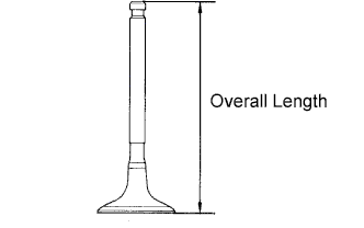
Using a vernier caliper, measure the valve's overall length.
Standard overall length 106.26 mm (4.1835 in.) Minimum overall length 105.96 mm (4.1716 in.) If the overall length is less than the minimum, replace the valve.
-
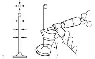
Using a micrometer, measure the diameter of the valve stem.
Standard valve stem diameter 5.470 to 5.485 mm (0.2154 to 0.2159 in.) -
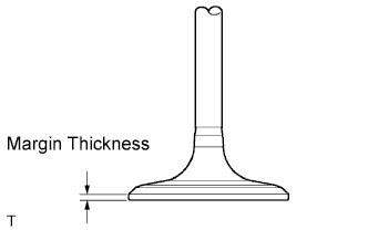
Using a vernier caliper, measure the valve head margin thickness.
Standard margin thickness 1.05 to 1.45 mm (0.0413 to 0.0571 in.) Minimum margin thickness 0.50 mm (0.0197 in.) If the margin thickness is less than the minimum, replace the valve.
-
-
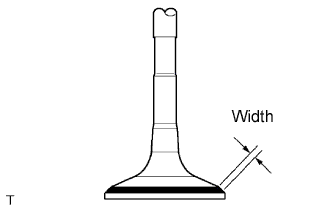
INSPECT EXHAUST VALVE
-
Using a vernier caliper, measure the valve's overall length.
Standard overall length 106.74 mm (4.2024 in.) Minimum overall length 106.44 mm (4.1905 in.) If the overall length is less than the minimum, replace the valve.
-
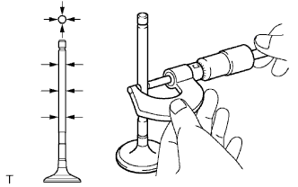
Using a micrometer, measure the diameter of the valve stem.
Standard valve stem diameter 5.465 to 5.480 mm (0.2151 to 0.2157 in.) -
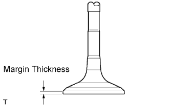
Using a vernier caliper, measure the valve head margin thickness.
Standard margin thickness 1.2 to 1.6 mm (0.0472 to 0.0630 in.) Minimum margin thickness 0.50 mm (0.0197 in.) If the margin thickness is less than the minimum, replace the valve.
-
-
INSPECT INTAKE VALVE GUIDE BUSH
-
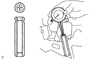
Using a caliper gauge, measure the inside diameter of the guide bush.
Bush inside diameter 5.510 to 5.530 mm (0.2169 to 0.2177 in.) -
Subtract the valve stem diameter measurement from the guide bush inside diameter measurement.
Standard oil clearance 0.025 to 0.060 mm (0.0010 to 0.0024 in.) Maximum oil clearance 0.08 mm (0.0032 in.) If the clearance is greater than the maximum, replace the valve and guide bush.
-
-
INSPECT EXHAUST VALVE GUIDE BUSH
-
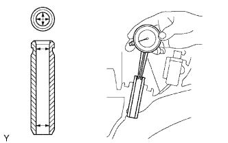
Using a caliper gauge, measure the inside diameter of the guide bush.
Standard bush inside diameter 5.510 to 5.530 mm (0.2169 to 0.2177 in.) -
Subtract the valve stem diameter measurement from the guide bush inside diameter measurement.
Standard oil clearance 0.030 to 0.065 mm (0.0012 to 0.0026 in.) Maximum oil clearance 0.10 mm (0.0039 in.) If the clearance is greater than the maximum, replace the valve and guide bush.
-
-
INSPECT NO. 1 BALANCE SHAFT
-
Inspect the diameter of the journal.
-
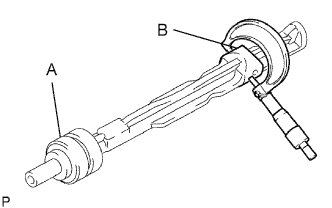
Using a micrometer, measure the diameter of the balance shaft main journals.
Standard main journal diameter Item Specified Condition A 37.969 to 37.985 mm (1.4948 to 1.4955 in.) B 37.449 to 37.465 mm (1.4744 to 1.4750 in.)
-
-
Inspect the diameter of bearing.
-
Using a cylinder gauge, measure the inside diameter of the balance shaft bearings.
Standard bearing inside diameter Item Specified Condition A 38.025 to 38.045 mm (1.4970 to 1.4978 in.) B 37.525 to 37.545 mm (1.4774 to 1.4781 in.)
-
-
Inspect the oil clearance.
-
Subtract the balance shaft main journal diameter measurement from the balance shaft bearing inside diameter measurement.
Standard oil clearance Item Specified Condition A 0.040 to 0.076 mm (0.0016 to 0.0030 in.) B 0.060 to 0.096 mm (0.0024 to 0.0038 in.) Maximum oil clearance 0.15 mm (0.0059 in.) If the oil clearance is greater than the maximum, replace the cylinder block and balance shaft.
-
-
-
INSPECT NO. 2 BALANCE SHAFT
-
Inspect the diameter of the journal.
-
Using a micrometer, measure the diameter of the balance shaft main journals.
Standard main journal diameter Item Specified Condition A 37.969 to 37.985 mm (1.4948 to 1.4955 in.) B 37.449 to 37.465 mm (1.4744 to 1.4750 in.)
-
-
Inspect the diameter of the bearing.
-
Using a cylinder gauge, measure the inside diameter of the balance shaft bearings.
Standard bearing inside diameter Item Specified Condition A 38.025 to 38.045 mm (1.4970 to 1.4978 in.) B 37.525 to 37.545 mm (1.4774 to 1.4781 in.)
-
-
Inspect the oil clearance.
-
Subtract the balance shaft main journal diameter measurement from the balance shaft bearing inside diameter measurement.
Standard oil clearance Item Specified Condition A 0.040 to 0.076 mm (0.0016 to 0.0030 in.) B 0.060 to 0.096 mm (0.0024 to 0.0038 in.) Maximum oil clearance 0.15 mm (0.0059 in.) If the oil clearance is greater than the maximum, replace the cylinder block and balance shaft.
-
-
-
INSPECT CYLINDER BLOCK
-
Inspect for flatness.
-
Using a precision straightedge and feeler gauge, measure the surface contacting the cylinder head gasket for warpage.
Maximum warpage 0.05 mm (0.0020 in.) If the warpage is greater than the maximum, replace the cylinder block.
-
-
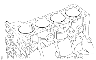
Visually check the cylinder for vertical scratches.
If deep scratches are present, rebore all the 4 cylinders. If necessary, replace the cylinder block.
-
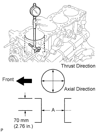
Inspect the cylinder bore diameter.
-
Using a cylinder gauge, measure the cylinder bore diameter at position A in the thrust and axial directions.
Standard diameter 94.990 to 95.003 mm (3.7398 to 3.7403 in.) If the diameter is greater than the maximum, rebore all the 4 cylinders. If necessary, replace the cylinder block.
-
-
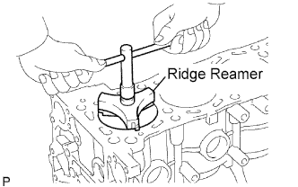
Inspect the cylinder ridge.
-
If the wear is less than 0.2 mm (0.008 in.), using a ridge reamer, grind the top of the cylinder.
-
-
-
INSPECT PISTON WITH PIN
-
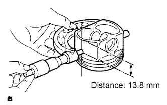
Inspect the piston oil clearance.
-
Using a micrometer, measure the piston diameter at right angles to the piston center line, the indicated distance from the piston end.
Standard distance 13.8 mm (0.543 in.) Standard piston diameter Item Specified Condition Standard side 94.940 to 94.950 mm (3.7378 to 3.7382 in.) O/S 0.50 95.440 to 95.450 mm (3.7575 to 3.7579 in.) -
Measure the cylinder bore diameter in the thrust directions.
-
Subtract the piston diameter measurement from the cylinder bore diameter measurement.
Standard oil clearance 0.019 to 0.052 mm (0.0007 to 0.0020 in.) If the oil clearance is greater than the standard, replace all the 4 pistons and rebore all the 4 cylinders. If necessary, replace the cylinder block.
-
-
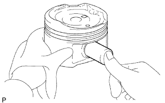
Inspect the piston pin fit.
-
At 60°C (140°F), check that the piston pin can be pushed into the piston pin hole with your thumb.
-
-
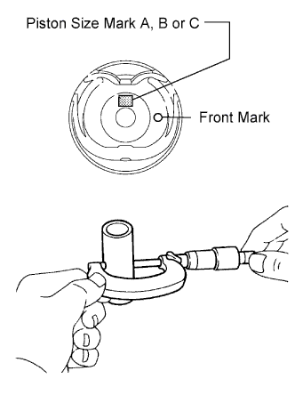
Inspect the piston pin diameter.
Tech Tips
There are 3 piston pin sizes, which are indicated by an A, B or C mark on its surface.
-
Using a micrometer, measure the piston pin diameter.
Standard piston pin diameter Mark Specified Condition A 21.997 to 22.000 mm
(0.8660 to 0.8661 in.)
B 22.001 to 22.003 mm
(0.8662 to 0.8663 in.)
C 22.004 to 22.006 mm
(0.8663 to 0.8664 in.)
D 22.007 to 22.009 mm
(0.8664 to 0.8665 in.)
If the diameter is not as specified, replace the piston pin and piston as a set.
-
-
-
INSPECT PISTON RING SET
-
Using a feeler gauge, measure the clearance between a new piston ring and the wall of the ring groove.
Standard ring groove clearance Item Specified Condition No. 1 ring 0.020 to 0.075 mm (0.0008 to 0.0030 in.) No. 2 ring 0.020 to 0.065 mm (0.0008 to 0.0026 in.) Oil ring 0.020 to 0.070 mm (0.0008 to 0.0028 in.) If the clearance is not as specified, replace the piston.
-
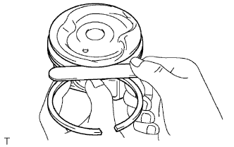
Inspect the piston ring end gap.
-
Insert the piston ring into the cylinder bore.
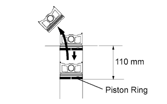
-
Using a piston, push the piston ring a little beyond the bottom of the ring travel, 110 mm (4.33 in.) from the top of the cylinder block.
-
Using a feeler gauge, measure the end gap.
Standard end gap Item Specified Condition No. 1 ring 0.22 to 0.34 mm (0.0087 to 0.0134 in.) No. 2 ring 0.45 to 0.57 mm (0.0177 to 0.0224 in.) Oil ring 0.10 to 0.40 mm (0.0039 to 0.0157 in.) Maximum end gap Item Specified Condition No. 1 ring 0.90 mm (0.0354 in.) No. 2 ring 1.36 mm (0.0535 in.) Oil ring 0.75 mm (0.0295 in.) If the end gap is greater than the maximum, replace the piston ring. If the end gap is greater than the maximum, even with a new piston ring, rebore all the 4 cylinders or replace the cylinder block.
-
-
-
INSPECT CONNECTING ROD
-
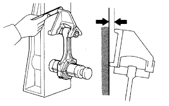
Using a rod aligner and feeler gauge, check the connecting rod alignment.
-
Check for bend.
Maximum bend 0.03 mm (0.0012 in.) per 100 mm (3.94 in.) If the bend is greater than the maximum, replace the connecting rod.
-
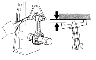
Check for twist.
Maximum twist 0.15 mm (0.0059 in.) per 100 mm (3.94 in.) If the twist is greater than the maximum, replace the connecting rod.
-
-
-
INSPECT PISTON PIN OIL CLEARANCE
Tech Tips
There is only 1 type of supply part for piston with pin.
-
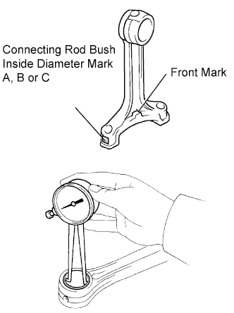
Inspect the piston pin oil clearance.
Tech Tips
There are 3 connecting rod bush sizes, which are indicated by an A, B or C mark on its surface.
-
Using a caliper gauge, measure the inside diameter of the connecting rod bush.
Standard bush inside diameter Mark Specified Condition A 22.005 to 22.008 mm (0.86633 to 0.86645 in.) B 22.008 to 22.011 mm (0.86645 to 0.86657 in.) C 22.011 to 22.014 mm (0.86657 to 0.86669 in.) -
Subtract the piston pin diameter measurement from the bush inside diameter measurement.
Standard oil clearance 0.001 to 0.007 mm (0.00004 to 0.00028 in.) Maximum oil clearance 0.01 mm (0.00039 in.) If the oil clearance is greater than the maximum, replace the connecting rod. If necessary, replace the piston and piston pin as a set.
-
-
-
INSPECT CONNECTING ROD BOLT
-
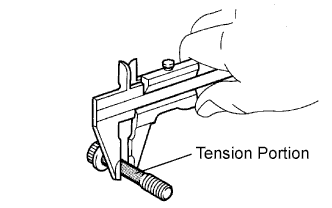
Using a vernier caliper, measure the tension portion diameter of the bolt.
Standard diameter 7.2 to 7.3 mm (0.283 to 0.287 in.) Minimum diameter 7.0 mm (0.276 in.) If the diameter is less than the minimum, replace the bolt.
-
-
INSPECT CRANKSHAFT
-
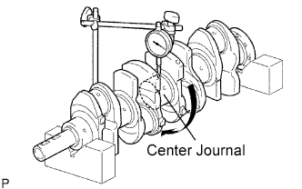
Inspect for circle runout.
-
Place the crankshaft on V-blocks.
-
Using a dial indicator, measure the circle runout at the center journal.
Maximum circle runout 0.03 mm (0.0012 in.) If the circle runout is greater than the maximum, replace the crankshaft.
-
-
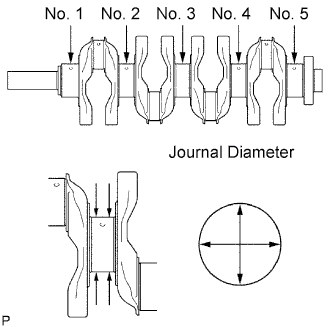
Inspect the main journals.
-
Using a micrometer, measure the diameter of each main journal.
Standard journal diameter Item Specified Condition No. 3 journal 59.981 to 59.994 mm (2.3615 to 2.3620 in.) Except No. 3 journal 59.987 to 60.000 mm (2.3229 to 2.3622 in.) If the diameter is not as specified, check the oil clearance. If necessary, replace the crankshaft.
-
Check each main journal for taper and out-of-round as shown in the illustration.
Maximum taper and out-of-round 0.005 mm (0.0002 in.) If the taper and out-of-round is greater than the maximum, replace the crankshaft.
-
-
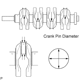
Inspect the crank pin.
-
Using a micrometer, measure the diameter of each crank pin.
Diameter 52.989 to 53.002 mm (2.0862 to 2.0867 in.) If the diameter is not as specified, check the oil clearance (see "INSPECT CONNECTING ROD OIL CLEARANCE" procedures). If necessary, replace the crankshaft.
-
Check each crank pin for taper and out-of-round as shown in the illustration.
Maximum taper and out-of-round 0.003 mm (0.0001 in.) If the taper and out-of-round is greater than the maximum, replace the crankshaft.
-
-
-
INSPECT CRANKSHAFT BEARING CAP SET BOLT
-

Using a vernier caliper, measure the minimum diameter of the elongated thread at the measuring point.
Standard outside diameter 10.76 to 10.97 mm (0.4236 to 0.4319 in.) Minimum outside diameter 10.66 mm (0.4197 in.) If the diameter is less than the minimum, replace the crankshaft bearing cap bolt.
-