ENGINE UNIT DISASSEMBLY

-
REMOVE OIL FILLER CAP
-
Remove the oil filler cap from the head cover.
-
-
REMOVE VENTILATION VALVE
-
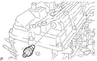
Remove the ventilation valve from the head cover.
-
-
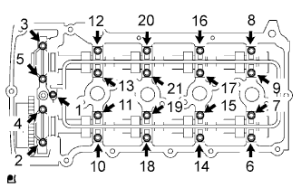
REMOVE CYLINDER HEAD COVER
-
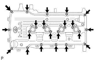
Remove the 19 bolts, 2 nuts, cover and 2 gaskets.
-
-
REMOVE CRANKSHAFT PULLEY
-
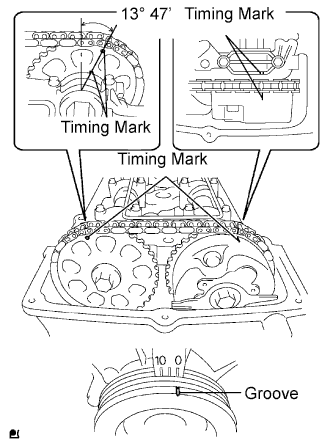
Turn the crankshaft pulley, and align its groove with timing mark 0 of the timing chain cover.
-
Check that the timing marks of the camshaft timing gear and sprocket are aligned with the timing marks of the No. 1 bearing cap, as shown in the illustration.
-
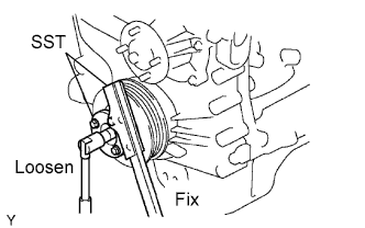
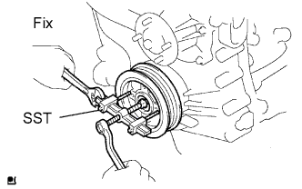
Using SST, hold the crankshaft pulley and remove the pulley set bolt.
- SST
- 09213-54015 ( 91651-60855 )
- 09330-00021
-
Using the pulley set bolt and SST, remove the pulley.
- SST
- 09950-50013 ( 09951-05010, 09952-05010, 09953-05010, 09954-05021 )
-
-
REMOVE NO. 2 OIL PAN
-
Remove the drain plug and gasket.
-
Remove the 20 bolts and 2 nuts.
-
Insert the blade of oil pan seal cutter between the oil pans. Cut through the applied sealer and remove the oil pan.
Note
Be careful not to damage the contact surfaces of the oil pans.
-
-
REMOVE OIL STRAINER
-
Remove the bolt, 2 nuts, oil strainer and gasket.
-
-
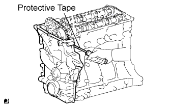
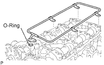
REMOVE NO. 1 OIL PAN
-
Remove the 16 bolts and 2 nuts.
-
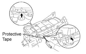
Remove the oil pan by prying between the oil pan and cylinder block with a screwdriver.
Tech Tips
Tape the screwdriver tip before use.
Note
Be careful not to damage the contact surfaces of the cylinder block and oil pan.
-
Remove the O-ring.
-
-
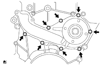
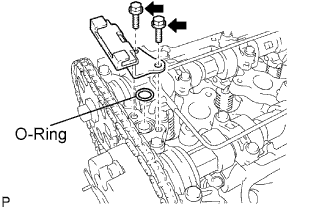
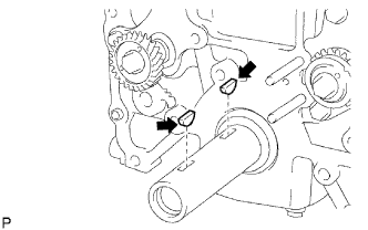
REMOVE TIMING CHAIN COVER
-
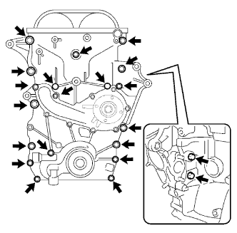
Remove the 19 bolts and 2 nuts shown in the illustration.
-
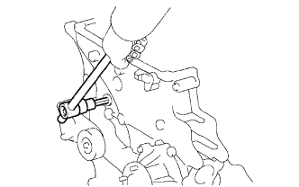
Remove the timing chain cover by prying between the timing chain cover and cylinder head or cylinder block with a screwdriver.
Tech Tips
Tape the screwdriver tip before use.
Note
Be careful not to damage the contact surfaces of the cylinder head, cylinder block and timing chain cover.
-
Remove the 3 O-rings.
-
Using a 10 mm socket hexagon wrench, remove the timing gear case plug.
-
-
REMOVE WATER PUMP
-
Remove the 8 bolts, water pump and gasket.
-
-
REMOVE TIMING CHAIN COVER OIL SEAL
-
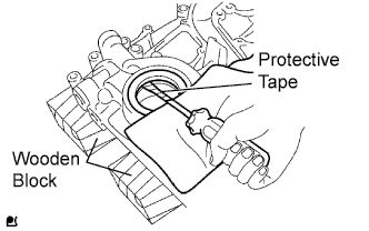
Place the timing chain cover on wooden blocks.
-
Using a screwdriver with its tip taped, pry out the oil seal.
-
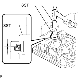
Using SST and a hammer, tap in a new oil seal until its surface is flush with the timing chain cover edge.
- SST
- 09223-75010
- 09950-70010 ( 09951-07150 )
Note
-
Keep the lip free from foreign matter.
-
Do not tap the oil seal at an angle.
Tech Tips
When installing the crankshaft pulley, check the shape of the pulley. The correct pulley has a groove Click here.
-
Apply a light coat of MP grease to a new oil seal lip.
-
-
REMOVE OIL PUMP RELIEF VALVE
-
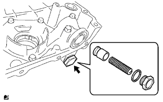
Using a 27 mm socket wrench, remove the plug and gasket.
-
Remove the valve spring and relief valve.
-
-
REMOVE TIMING CHAIN GUIDE
-
Remove the 2 bolts, timing chain guide and O-ring.
-
-
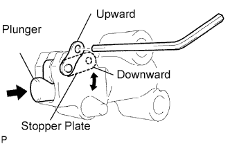
REMOVE NO. 1 TIMING CHAIN TENSIONER
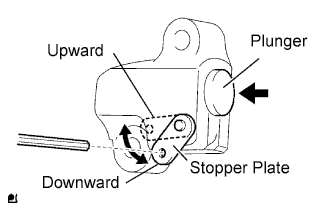
Note
-
When the chain tensioner is removed, do not rotate the crankshaft.
-
When the chain is removed and the camshaft needs to be rotated, rotate the crankshaft 90° to the right.
-
Move the stopper plate upward to release the lock, and push the plunger deep into the tensioner.
-
Move the stopper plate downward to set the lock, and insert a hexagon wrench into the stopper plate's hole.
-
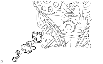
Remove the bolt, nut, chain tensioner and gasket.
-
-
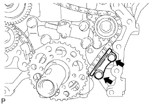
REMOVE CHAIN TENSIONER SLIPPER
-
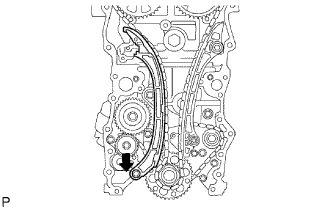
Remove the bolt and tensioner slipper.
-
-
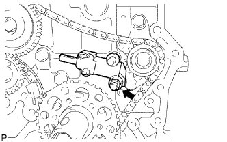
REMOVE NO. 1 VIBRATION DAMPER
-
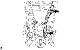
Remove the bolt, nut and vibration damper.
-
-
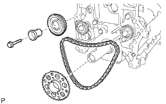
REMOVE TIMING CHAIN
-
REMOVE CRANKSHAFT TIMING SPROCKET
-
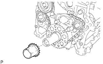
Remove the crankshaft timing sprocket from the crankshaft.
-
-
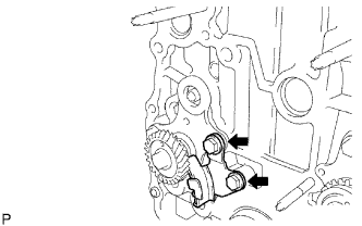
REMOVE CRANKSHAFT POSITION SENSOR PLATE
-
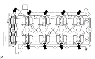
REMOVE CAMSHAFT
-
Uniformly loosen the 21 bearing cap bolts in the several passes in the order shown in the illustration.
-
Remove the 9 bearing caps, oil delivery pipe, O-ring and 2 camshafts.
Note
-
Place the camshaft on a flat surface, maintain this position and loosen the bolts uniformly.
-
Do not pry the camshaft with a tool by applying excessive force to it.
-
Do not damage the reception part of the exhaust on the cylinder head side.
-
-
Remove the oil delivery pipe and O-ring from the bearing caps.
-
Remove the 9 bearing caps.
-
Remove the 2 camshafts.
-
-
REMOVE CAMSHAFT TIMING SPROCKET
-
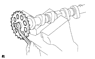
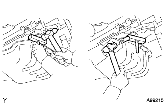
Fix the camshaft with a vise, and then remove the sprocket bolt and camshaft timing sprocket.
Note
Be careful not to damage the camshaft.
-
-
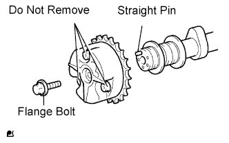
REMOVE CAMSHAFT TIMING GEAR
-
Remove the flange bolt of the camshaft timing gear.
Note
-
Be sure not to remove the other 3 bolts.
-
If planning to reuse the gear, be sure to release the straight pin lock before installing the gear.
-
-
-
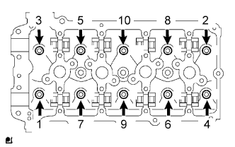
REMOVE CYLINDER HEAD
-
Using a 10 mm bi-hexagon wrench, uniformly loosen the 10 bolts in the sequence shown in the illustration. Remove the 10 cylinder head bolts and plate washers.
Note
-
Be careful not to drop washers into the cylinder head.
-
Head warpage or cracking could result from removing bolts in an incorrect order.
-
-
Remove the cylinder head and gasket.
-
-
REMOVE NO. 2 CHAIN VIBRATION DAMPER
-
Move the stopper plate downward to release the lock, and push the plunger deep into the tensioner.
-
Move the stopper plate upward to set the lock, and insert a hexagon wrench into the stopper plate's hole.
-
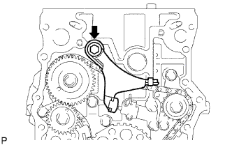
Remove the bolt and chain vibration damper.
-
-
REMOVE NO. 3 CHAIN VIBRATION DAMPER
-
Remove the 2 bolts and chain vibration damper.
-
-
REMOVE NO. 2 CHAIN TENSIONER
-
Remove the hexagon wrench from the tensioner.
-
Remove the nut and chain tensioner.
-
-
REMOVE NO. 2 CHAIN
-
Remove the bolt, balance shaft drive gear shaft and balance shaft drive gear.
-
Remove the No. 2 crankshaft timing sprocket and chain.
-
-
REMOVE NO. 4 CHAIN VIBRATION DAMPER
-
Remove the 2 bolts and No. 4 vibration damper.
-
-
REMOVE CRANKSHAFT PULLEY SET KEY
-
Remove the 2 pulley set keys from the crankshaft.
-
-
REMOVE OIL FILTER
-
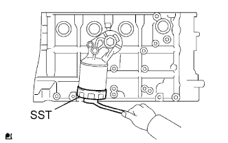
Using SST, remove the oil filter.
- SST
- 09228-07501
-
-
REMOVE OIL FILTER UNION
-
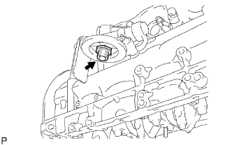
Using a 27 mm socket wrench, remove the oil filter union.
-
-
REMOVE OIL FILTER BRACKET
-
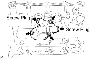
Remove the 2 screw plugs and 2 gaskets from the oil filter bracket.
-
Remove the 2 bolts, nut and oil filter bracket.
-
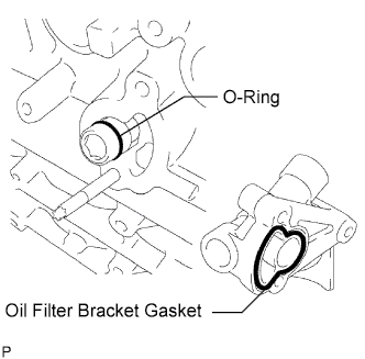
Remove the gasket and O-ring.
-
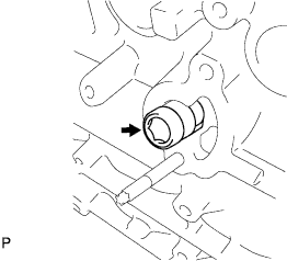
Using a 14 mm hexagon wrench, remove the oil filter bracket union.
-
-
REMOVE ENGINE REAR OIL SEAL RETAINER
-
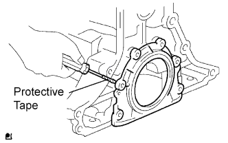
Remove the 6 bolts.
-
Using a screwdriver with its tip taped, pry out the oil seal retainer.
-
-
REMOVE VALVE ROCKER ARM
Tech Tips
Each rocker arm must be reinstalled to its original location.
-
REMOVE VALVE STEM CAP
Tech Tips
Each valve stem cap must be reinstalled to its original location.
-
REMOVE VALVE LASH ADJUSTER
Tech Tips
Each lash adjuster must be reinstalled to its original location.
-
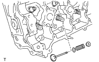
REMOVE INTAKE VALVE
-
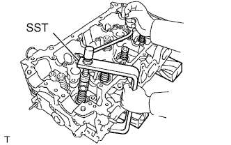
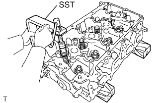
Using SST and wooden blocks, compress the compression spring and remove the valve retainer locks.
- SST
- 09202-70020 ( 09202-00010 )
-
Remove the retainer, compression spring, valve, valve spring and spring seat.
Tech Tips
Each intake valve must be reinstalled to its original location.
-
-
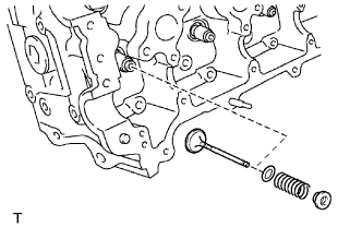
REMOVE EXHAUST VALVE
-
Using SST and wooden blocks, compress the compression spring and remove the valve retainer locks.
-
Remove the retainer, compression spring, valve, valve spring and spring seat.
Tech Tips
Each exhaust valve must be reinstalled to its original location.
-
-
REMOVE VALVE STEM OIL SEAL
-
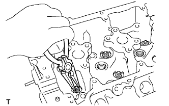
Using needle-nose pliers, remove the oil seal.
-
-
REMOVE OIL CONTROL VALVE FILTER
-
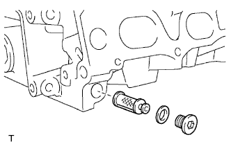
Using an 8 mm hexagon wrench, remove the screw plug.
-
Remove the oil control valve filter and gasket.
-
-
REMOVE NO. 1 STRAIGHT SCREW PLUG
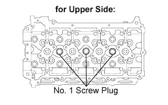
-
Using a 10 mm hexagon wrench, remove the 3 screw plugs.
-
-
REMOVE NO. 2 STRAIGHT SCREW PLUG
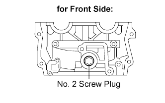
-
Using a 9 mm hexagon wrench, remove the screw plug.
-
-
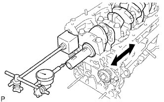
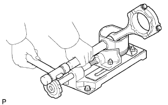
INSPECT CONNECTING ROD THRUST CLEARANCE
-
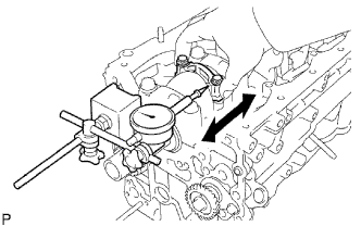
Using a dial indicator, measure the thrust clearance while moving the connecting rod back and forth.
Standard thrust clearance 0.15 to 0.35 mm (0.006 to 0.014 in.) Maximum thrust clearance 0.40 mm (0.016 in.) If the thrust clearance is greater than the maximum, replace the connecting rod assembly(s). If necessary, replace the crankshaft.
-
-
INSPECT CONNECTING ROD OIL CLEARANCE
-
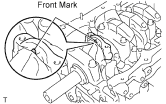
Check that the front mark on the connecting rod and cap are aligned to ensure the correct reassembly.
Tech Tips
The front mark on the connecting rods and caps are for ensuring the correct reassembly.
-
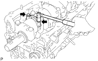
Remove the 2 connecting rod cap bolts.
-
Using the 2 removed connecting rod cap bolts, remove the connecting rod cap and lower bearing by wiggling the connecting rod cap right and left.
Tech Tips
Keep the lower bearing inserted to the connecting rod cap.
-
Clean the crank pin and bearing.
-
Check the crank pin and bearing for pitting and scratches.
-
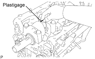
Lay a strip of Plastigage on the crank pin.
-
Install the connecting rod cap.
Note
Do not turn the crankshaft.
-
Match the numbered connecting rod cap with the connecting rod.
-
Align the pins of the connecting rod cap with the pin holes of the connecting rod, and install the connecting rod cap.
-
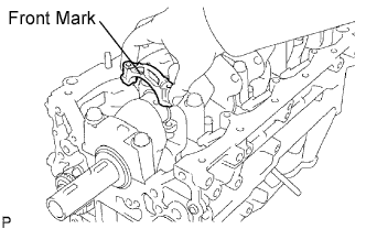
Check that the front mark of the connecting rod cap is facing forward.
-
-
Install the connecting rod cap bolts.
Tech Tips
-
The connecting rod cap bolts are tightened in 2 progressive steps.
-
If any connecting rod bolt is broken or deformed, replace it.
-
Apply a light coat of engine oil on the threads and under the heads of the connecting rod cap bolts.
-
Install and alternately tighten the bolts of the connecting rod cap in several passes.
- Torque:
- 24.5 N*m { 250 kgf*cm, 18 ft.*lbf }
If any one of the connecting rod cap bolts does not meet the torque specification, replace the cap bolts.
-
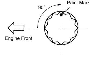
Mark the front of the connecting rod cap bolts with paint.
-
Retighten the connecting rod cap bolts 90° as shown.
-
Check that the painted mark is now at a 90° angle to the front.
-
-
Remove the 2 bolts and connecting rod cap.
-
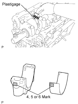
Measure the Plastigage at its widest point.
Standard oil clearance 0.039 to 0.066 mm (0.0015 to 0.0026 in.) If the crank pin or bearing is damaged, replace the bearings. If necessary, replace the crankshaft.
Tech Tips
If replacing a bearing, replace it with one that has the same number as its respective connecting rod cap. Each bearing's standard thickness is indicated by a 4, 5 or 6 mark on its surface.
Standard bearing center wall thickness Mark Specified Condition 4 1.484 to 1.487 mm (0.0584 to 0.0585 in.) 5 1.488 to 1.490 mm (0.0586 to 0.0587 in.) 6 1.491 to 1.493 mm (0.0587 to 0.0588 in.) -
Completely remove the Plastigage.
-
-
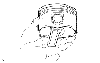
REMOVE PISTON WITH CONNECTING ROD
-
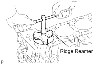
Using a ridge reamer, remove all the carbon from the top of the cylinder.
-
Push the piston, connecting rod assembly and upper bearing through the top of the cylinder block.
Tech Tips
-
Keep the bearing, connecting rod and cap together.
-
Arrange the piston and connecting rod assemblies in the correct order.
-
-
-
INSPECT CRANKSHAFT THRUST CLEARANCE
-
Using a dial indicator, measure the thrust clearance while prying the crankshaft back and forth with a screwdriver.
Standard thrust clearance 0.020 to 0.220 mm (0.0008 to 0.0087 in.) Maximum thrust clearance 0.30 mm (0.0118 in.) If the thrust clearance is greater than the maximum, replace the thrust washers as a set.
Thrust washer thickness 2.440 to 2.490 mm (0.0961 to 0.0980 in.)
-
-
INSPECT CRANKSHAFT OIL CLEARANCE
Tech Tips
Before performing this procedure, make sure to check the procedure selection chart, as there are different types of crankshafts and cylinder blocks.
Note
Only perform the procedure for type C when there are letters for the cylinder block journal code and there is a crankshaft journal code.
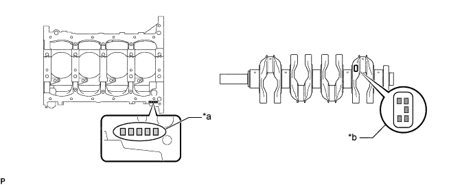
Text in Illustration *a Cylinder Block Journal Code *b Crankshaft Journal Code Procedure Selection Chart - No Journal Code on Crankshaft Journal Code on Crankshaft Cylinder Block Journal Code (Numbers) Type A Type A Cylinder Block Journal Code (Letters) Type B Type C
-
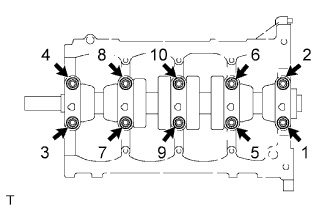
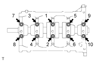
Uniformly loosen the 10 bearing cap bolts in several passes in the sequence shown in the illustration.
Tech Tips
-
Keep the lower bearings and crankshaft bearing caps together.
-
Arrange the thrust washers in the correct order.
-
-
Clean each main journal and bearing.
-
Check each main journal and bearing for pitting and scratches.
If the journal or bearing is damaged, replace the bearings. If necessary, grind or replace the crankshaft.
-
Place the crankshaft on the cylinder block.
-
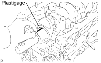
Lay a strip of Plastigage across each journal.
-
Install the 5 crankshaft bearing caps in their proper locations.
Note
Do not turn the crankshaft.
-
Install the crankshaft bearing cap bolts.
Tech Tips
-
The main bearing cap bolts are tightened in 2 progressive steps.
-
If any of the main bearing cap bolts are broken or deformed, replace as necessary.
-
Install and uniformly tighten the 10 main bearing cap bolts in the sequence shown in the illustration.
- Torque:
- 39 N*m { 398 kgf*cm, 29 ft.*lbf }
If any one of the main bearing cap bolts does not meet the torque specification, replace the main bearing cap bolt.
-
Mark the front of the bearing cap bolts with paint.
-
Retighten the bearing cap bolts by 90° in the numerical order above.
-
Check that the painted mark is now at a 90° angle to the front.
-
-
Remove the 10 bolts and 5 crankshaft bearing caps.
-
Check the type of crankshaft journal code and cylinder block journal code and select an inspection procedure.
Text in Illustration *a Cylinder Block Journal Code *b Crankshaft Journal Code Procedure Selection Chart - No Journal Code on Crankshaft Journal Code on Crankshaft Cylinder Block Journal Code (Numbers) Type A Type A Cylinder Block Journal Code (Letters) Type B Type C Note
Only perform the procedure for type C when there are letters for the cylinder block journal code and there is a crankshaft journal code.
-
for Type A:
-
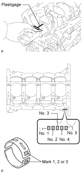
Measure the Plastigage at its widest point.
Standard Oil Clearance Item Specified Condition No. 3 journal 0.030 to 0.055 mm (0.0012 to 0.0022 in.) Other journal 0.024 to 0.049 mm (0.0009 to 0.0019 in.) Maximum oil clearance 0.10 mm (0.0039 in.) If the oil clearance is more than the maximum, replace the crankshaft bearing.
If replacing the cylinder block, measure the bearing standard clearance.
If replacing a bearing, first check the number on the cylinder block for the bearing's respective journal. Then replace the bearing with one that has the same number. Each bearing's standard thickness is indicated by a 1, 2 or 3 mark on its surface.
Cylinder Block Main Journal Bore Diameter Item Specified Condition Mark 1 64.004 to 64.010 mm (2.5198 to 2.5201 in.) Mark 2 64.011 to 64.016 mm (2.5201 to 2.5203 in.) Mark 3 64.017 to 64.022 mm (2.5203 to 2.5206 in.) Standard Bearing Center Wall Thickness Item Specified Condition Mark 1 1.987 to 1.990 mm (0.07823 to 0.07835 in.) Mark 2 1.991 to 1.993 mm (0.07839 to 0.07846 in.) Mark 3 1.994 to 1.996 mm (0.07850 to 0.07858 in.)
-
-
for Type B:
-
Measure the Plastigage at its widest point.
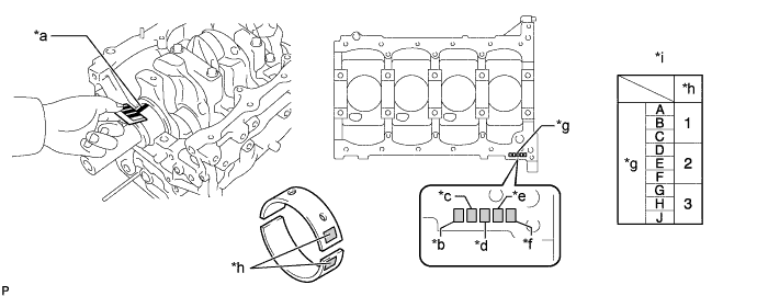
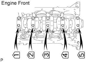
Text in Illustration *a Plastigage *b No. 1 Journal *c No. 2 Journal *d No. 3 Journal *e No. 4 Journal *f No. 5 Journal *g Cylinder Block Journal Code *h Crankshaft Bearing Code *i Bearing Code Chart - - Standard Oil Clearance Item Specified Condition No. 3 journal 0.030 to 0.055 mm (0.0012 to 0.0022 in.) Other journal 0.024 to 0.049 mm (0.0009 to 0.0019 in.) Maximum oil clearance 0.10 mm (0.0039 in.) If the oil clearance is more than the maximum, replace the crankshaft bearing.
If replacing the cylinder block, measure the bearing standard clearance.
Check the cylinder block journal code and refer to the crankshaft bearing selection chart to select a bearing size.
(Example): When the cylinder block journal code is "D", select crankshaft bearing selection code "2" from the crankshaft bearing selection chart.
Cylinder Block Main Journal Bore Diameter Item Specified Condition Mark A 64.004 to 64.006 mm (2.51984 to 2.51992 in.) Mark B 64.007 to 64.008 mm (2.51996 to 2.51999 in.) Mark C 64.009 to 64.010 mm (2.52003 to 2.52007 in.) Mark D 64.011 to 64.012 mm (2.52011 to 2.52015 in.) Mark E 64.013 to 64.014 mm (2.52019 to 2.52023 in.) Mark F 64.015 to 64.016 mm (2.52027 to 2.52031 in.) Mark G 64.017 to 64.018 mm (2.52035 to 2.52039 in.) Mark H 64.019 to 64.020 mm (2.52043 to 2.52047 in.) Mark J 64.021 to 64.022 mm (2.52051 to 2.52055 in.) Standard Bearing Center Wall Thickness Item Specified Condition Mark 1 1.987 to 1.990 mm (0.07823 to 0.07835 in.) Mark 2 1.991 to 1.993 mm (0.07839 to 0.07846 in.) Mark 3 1.994 to 1.996 mm (0.07850 to 0.07858 in.)
-
-
for Type C:
-
Measure the Plastigage at its widest point.
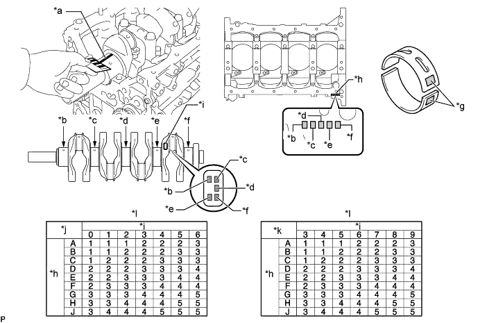
Text in Illustration *a Plastigage *b No. 1 Journal *c No. 2 Journal *d No. 3 Journal *e No. 4 Journal *f No. 5 Journal *g Crankshaft Bearing Code *h Cylinder Block Journal Code *i Crankshaft Journal Code *j #1J, #2J, #4J, #5J *k #3J *l Bearing Code Chart Standard Oil Clearance Item Specified Condition No. 3 journal 0.030 to 0.044 mm (0.00118 to 0.00173 in.) Other journal 0.024 to 0.038 mm (0.000945 to 0.00150 in.) Maximum oil clearance 0.10 mm (0.0039 in.) If the oil clearance is more than the maximum, replace the crankshaft bearing.
If replacing the cylinder block, measure the bearing standard clearance.
Check the cylinder block journal code and crankshaft journal code and refer to the crankshaft bearing selection chart to select a bearing size.
(Example) (Excluding No. 3 journal): When the cylinder block journal code is "D" and the crankshaft journal code is "4", select crankshaft bearing selection code "3" from the crankshaft bearing selection chart.
Cylinder Block Main Journal Bore Diameter Item Specified Condition Mark A 64.004 to 64.006 mm (2.51984 to 2.51992 in.) Mark B 64.007 to 64.008 mm (2.51996 to 2.51999 in.) Mark C 64.009 to 64.010 mm (2.52003 to 2.52007 in.) Mark D 64.011 to 64.012 mm (2.52011 to 2.52015 in.) Mark E 64.013 to 64.014 mm (2.52019 to 2.52023 in.) Mark F 64.015 to 64.016 mm (2.52027 to 2.52031 in.) Mark G 64.017 to 64.018 mm (2.52035 to 2.52039 in.) Mark H 64.019 to 64.020 mm (2.52043 to 2.52047 in.) Mark J 64.021 to 64.022 mm (2.52051 to 2.52055 in.) Crankshaft Journal Bore Diameter Item Specified Condition (Other Journal) Specified Condition (No. 3 Journal) Mark 0 59.999 to 60.000 mm (2.36216 to 2.36220 in.) - Mark 1 59.997 to 59.998 mm (2.36208 to 2.36212 in.) - Mark 2 59.995 to 59.996 mm (2.36200 to 2.36204 in.) - Mark 3 59.993 to 59.994 mm (2.36192 to 2.36196 in.) 59.993 to 59.994 mm (2.36192 to 2.36196 in.) Mark 4 59.991 to 59.992 mm (2.36185 to 2.36189 in.) 59.991 to 59.992 mm (2.36185 to 2.36189 in.) Mark 5 59.989 to 59.990 mm (2.36177 to 2.36181 in.) 59.989 to 59.990 mm (2.36177 to 2.36181 in.) Mark 6 59.987 to 59.988 mm (2.36169 to 2.36173 in.) 59.987 to 59.988 mm (2.36169 to 2.36173 in.) Mark 7 - 59.985 to 59.986 mm (2.36161 to 2.36165 in.) Mark 8 - 59.983 to 59.984 mm (2.36153 to 2.36157 in.) Mark 9 - 59.981 to 59.982 mm (2.36145 to 2.36149 in.) Standard Bearing Center Wall Thickness Item Specified Condition Mark 1 1.987 to 1.990 mm (0.07823 to 0.07835 in.) Mark 2 1.991 to 1.993 mm (0.07839 to 0.07846 in.) Mark 3 1.994 to 1.996 mm (0.07850 to 0.07858 in.) Mark 4 1.997 to 1.999 mm (0.07862 to 0.07870 in.) Mark 5 2.000 to 2.002 mm (0.07874 to 0.07882 in.)
-
-
Completely remove the Plastigage.
-
-
REMOVE CRANKSHAFT
-
Lift out the crankshaft.
Tech Tips
Keep the upper crankshaft bearings and upper thrust washers together with the cylinder block.
-
-
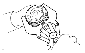
REMOVE PISTON WITH PIN
-
Check fit between the piston and piston pin.
-
Try to move the piston back and forth on the piston pin.
If any movement is felt, replace the piston and pin as a set.
-
-
Remove the piston rings.
-
Using a piston ring expander, remove the 2 compression rings.
-
Remove the rail and expander by hand.
Tech Tips
Arrange the piston rings in the correct order only.
-
-
Disconnect the connecting rod from the piston.
-
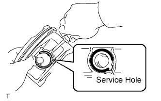
Using a small screwdriver, pry off the snap ring from the piston.
-
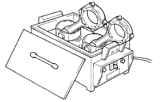
Gradually heat the piston to approximately 80 to 90°C (176 to 194°F).
-
Using a brass bar and plastic-faced hammer, lightly tap out the piston pin and remove the connecting rod.
Tech Tips
-
The piston and pin are a matched set.
-
Arrange the pistons, pins, rings, connecting rods and bearings in the correct order.
-
-
-
-
REMOVE CYLINDER BLOCK WATER DRAIN COCK
-
REMOVE OIL NOZZLE
-
Using a 5 mm hexagon wrench, remove the oil nozzle.
-
-
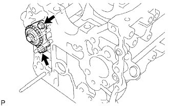
INSPECT BALANCE SHAFT THRUST CLEARANCE
-
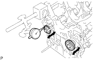
Using a dial indicator, measure the thrust clearance while moving the balance shaft back and forth.
Standard thrust clearance 0.07 to 0.13 mm (0.0027 to 0.0051 in.) Maximum thrust clearance 0.20 mm (0.0079 in) If the thrust clearance is greater than the maximum, replace the balance shaft thrust washer. If necessary, replace the balance shaft.
-
-
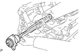
REMOVE NO. 1 BALANCE SHAFT
-
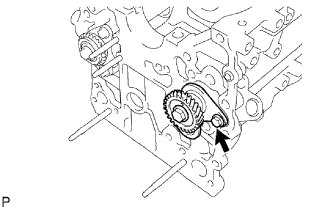
Remove the bolt.
-
Remove the balance shaft from the cylinder block.
Note
When removing the balance shaft, make sure to support the balance shaft with both hands and avoid scratching the balance shaft bearing on the cylinder block side.
-
-
REMOVE NO. 1 BALANCE SHAFT DRIVEN GEAR
-
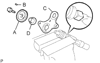
Mount the head portion of the balance shaft in a vise.
Note
Be careful not to damage the balance shaft.
-
Remove the bolt.
-
Remove the No. 1 balance shaft driven gear (A), sliding key (B), No. 1 balance shaft thrust washer (C) and balance shaft thrust spacer (D).
-
-
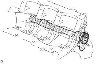
REMOVE NO. 2 BALANCE SHAFT
-
Remove the 2 bolts.
-
Remove the balance shaft from the cylinder block.
Note
When removing the balance shaft, make sure to support the balance shaft with both hands and avoid scratching the balance shaft bearing on the cylinder block side.
-
-
REMOVE NO. 2 BALANCE SHAFT DRIVEN GEAR
-
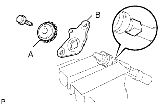
Mount the head portion of the balance shaft in a vise.
Note
Be careful not to damage the balance shaft.
-
Remove the bolt.
-
Remove the No. 2 balance shaft driven gear (A) and No. 2 balance shaft thrust washer (B).
-