CAMSHAFT INSTALLATION

-
INSTALL CAMSHAFT TIMING GEAR
-
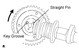
Put the camshaft timing gear and camshaft together by aligning the key groove and straight pin.
-
Check that there is no gap between the gear's flange and the camshaft.
-
With the camshaft timing gear fixed in place, tighten the flange bolt.
- Torque:
- 78 N*m { 795 kgf*cm, 58 ft.*lbf }
-
-
INSTALL VALVE STEM CAP
-
Apply clean engine oil to the valve stem tip, and install the valve stem cap.
Note
Install the cap to the same place it was removed from.
-
-
INSTALL VALVE LASH ADJUSTER
Note
-
Keep the lash adjuster free from dirt and foreign objects.
-
Only use clean engine oil.
-
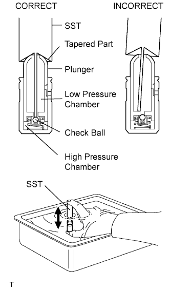
Place the lash adjuster into a container full of engine oil.
-
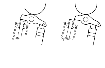
Insert SST's tip into the lash adjuster's plunger and use the tip to press down on the checkball inside the plunger.
- SST
- 09276-75010
-
Squeeze the SST and lash adjuster together to move the plunger up and down 5 to 6 times.
-
Check the movement of the plunger and bleed air.
OK Plunger moves up and down. Note
When bleeding high-pressure air from the compression chamber, make sure that the tip of the SST is actually pressing the checkball as shown in the illustration. If the checkball is not pressed, air will not bleed.
-
After bleeding air, remove SST. Then, try to quickly and firmly press the plunger with a finger.
OK Plunger is very difficult to move. If the result is not as specified, replace the lash adjuster.
-
Install the lash adjuster.
Tech Tips
Repeat the same procedures and install the remaining lash adjusters.
Note
Install the lash adjuster to the same place it was removed from.
-
-
INSTALL VALVE ROCKER ARM
-
Apply clean engine oil to the valve lash adjuster tips and valve stem cap surfaces. Then install the valve rocker arms.
Note
Install the valve stem cap and valve rocker arm to the same place it was removed from.
-
-
INSTALL CAMSHAFT
-
Apply clean engine oil to the camshaft's cam portion and the cylinder head journals.
-
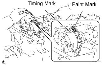
Install the timing chain on the camshaft timing gear, with the painted mark of the link aligned with the timing mark of the camshaft timing gear.
-
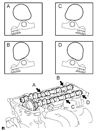
Set the 2 camshafts as shown in the illustration.
Note
-
Align the paint mark and timing mark before setting the camshaft.
-
Before and after setting the camshaft and No. 2 camshaft, check that the rocker arm is firmly set to the lash adjuster.
-
-
Loosely install the No. 1 camshaft bearing cap.
-
Check the proper location of each camshaft bearing cap and install each one.
-
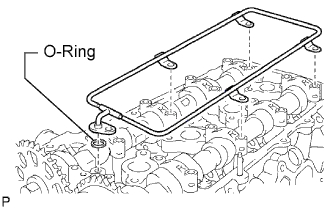
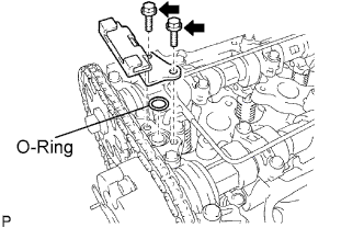
Install a new O-ring to the No. 1 camshaft bearing cap.
-
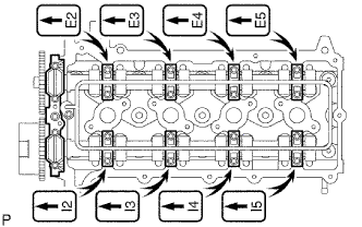
Temporarily install the oil delivery pipe.
-
Tighten the 21 bolts and 20 washers in the order shown in the illustration.
- Torque:
- 12 N*m { 122 kgf*cm, 9 ft.*lbf, for bolt A }
- 15.5 N*m { 158 kgf*cm, 11 ft.*lbf, for except bolt A }
-
-
INSTALL CAMSHAFT TIMING SPROCKET
-
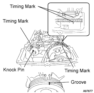
Rotate the camshaft so that the camshaft's timing mark and the No. 2 camshaft knock pin are as shown in the illustration.
-
Turn the crankshaft pulley, and align its groove with timing mark 0 of the timing chain cover.
-
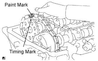
Install the timing chain on the camshaft timing sprocket, with the paint mark aligned with the timing marks on the camshaft timing sprocket.
-
Align the No. 2 camshaft knock pin and camshaft timing sprocket's pin hole. Then install the camshaft timing sprocket to the No. 2 camshaft.
Note
If the knock pin and pin hole are difficult to align, slightly rotate the No. 2 camshaft to the left and right using the camshaft's hexagon-shaped part. Then attempt alignment again.
-
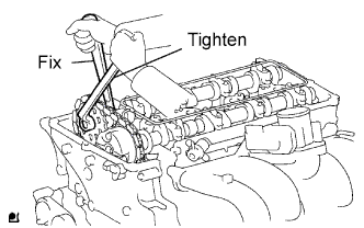
Fix the camshaft with a wrench, and then tighten the sprocket bolt.
- Torque:
- 78 N*m { 795 kgf*cm, 58 ft.*lbf }
-
Remove the hexagon wrench from the chain tensioner.
-
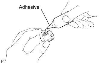
Apply adhesive to 2 or 3 threads of the timing chain cover plug.
Adhesive Toyota Genuine Adhesive 1324, Three Bond 1324 or equivalent Note
Remove any oil from the bolt hole.
-
Using a 10 mm socket hexagon wrench, install the timing gear case plug.
- Torque:
- 16.6 N*m { 169 kgf*cm, 12 ft.*lbf }
-
-
INSTALL TIMING CHAIN GUIDE
-
Install a new O-ring to the camshaft bearing cap.
-
Install the timing chain guide with the 2 bolts.
- Torque:
- 10 N*m { 102 kgf*cm, 7 ft.*lbf }
-
-
INSTALL CYLINDER HEAD COVER
-

Install the 2 gaskets to the cylinder head cover.
-
Remove any old packing (FIPG) material.
-
Apply seal packing to 2 locations as shown in the illustration.
Seal packing Toyota Genuine Seal Packing Black, Three Bond 1207B or equivalent Note
-
Remove any oil from the contact surface.
-
Install the cylinder head cover within 3 minutes after applying seal packing.
-
Do not apply engine oil for at least 2 hours after installing.
-
-
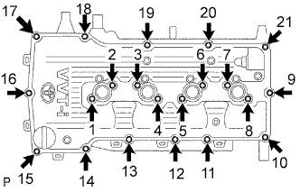
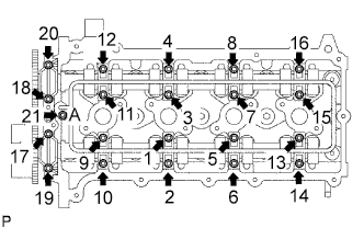
Loosely install the head cover with the 19 bolts and 2 nuts.
-
Uniformly tighten the 19 bolts and 2 nuts in the sequence shown in the illustration.
- Torque:
- 9.0 N*m { 92 kgf*cm, 80 in.*lbf }
-
In numerical order, confirm that the bolts labeled 1 to 18 are tightened to the torque specification. Tighten the bolts as necessary.
-
Connect the wire harness to the 6 clamps.
-
-
INSTALL IGNITION COIL
-
Install the ignition coil with the bolt.
- Torque:
- 9.0 N*m { 92 kgf*cm, 80 in.*lbf }
-
-
INSTALL INTAKE AIR CONNECTOR
-
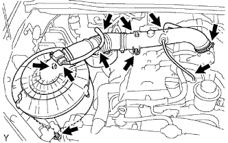
Install the air cleaner and intake air connector assembly with the 4 bolts, and tighten the hose clamp.
- Torque:
- 14 N*m { 143 kgf*cm, 10 ft.*lbf, for air cleaner }
- 8.0 N*m { 82 kgf*cm, 71 in.*lbf, for intake air connector }
- 5.0 N*m { 51 kgf*cm, 44 in.*lbf, for hose clamp }
-
Connect the MAF meter connector and harness clamps.
-
Connect the No. 2 ventilation hose.
-
Connect the vacuum hose.
-
-
INSTALL DRIVE BELT
-
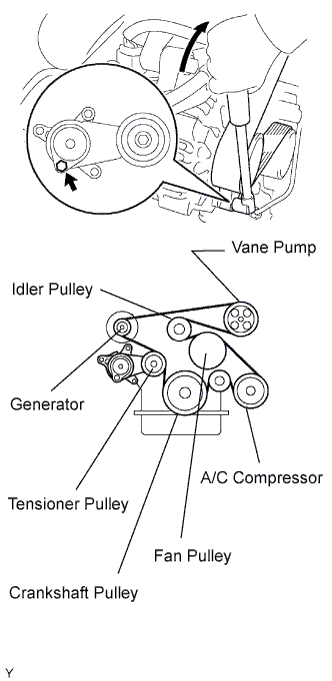
Install the drive belt to the pulleys except the drive belt tensioner pulley.
-
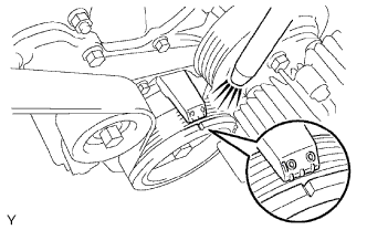
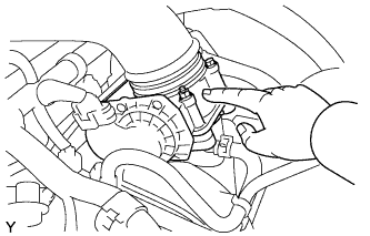
Use the hexagon-shaped part indicated by the arrow in the illustration to move the tensioner pulley downward and then install the drive belt to the tensioner pulley.
Note
-
The backside of the drive belt should face the tensioner pulley.
-
Check that the drive belt is properly set to each pulley.
-
-
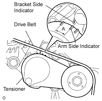
After a new belt has been installed, check that the tensioner indicator mark is within range A shown in the illustration.
-
-
CONNECT CABLE TO NEGATIVE BATTERY TERMINAL
-
PERFORM INITIALIZATION
-
Perform initialization Click here.
Note
Certain systems need to be initialized after disconnecting and reconnecting the cable from the negative (-) battery terminal.
-
-
CHECK FOR ENGINE OIL LEAKS
-
Start the engine, and check that there are no oil leaks after performing maintenance.
-
-
CHECK FOR ENGINE COOLANT LEAKS
CAUTION:
Do not remove the radiator cap while the engine and radiator are still hot. Pressurized, hot engine coolant and steam may be released and cause serious burns.
-
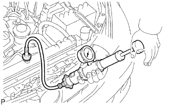
Fill the radiator with coolant and attach a radiator cap tester.
-
Warm up the engine.
-
Using a radiator cap tester, increase the pressure inside the radiator to 118 kPa (1.2 kgf/cm2, 17.1 psi), and check that the pressure does not drop.
If the pressure drops, check the hoses, radiator and water pump for leaks. If no external leaks are found, check the cylinder block and head.
-
-
CHECK IGNITION TIMING
-
Warm up the engine and stop the engine.
Note
A warmed up engine should have an engine coolant temperature of over 80°C (176°F), have an engine oil temperature of 60°C (140°F), and the engine rpm should be stabilized.
-
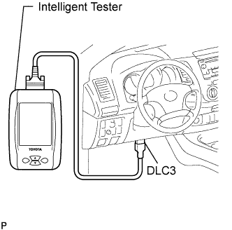
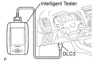
When using the intelligent tester:
Check the ignition timing.
-
Connect the intelligent tester to the DLC3.
-
Start the engine at idle.
-
Turn the intelligent tester main switch ON.
-
Enter the following item: Powertrain / Engine and ECT / Data List / IGN Advance.
Standard ignition timing 0 to 20° BTDC @ idle Tech Tips
Please refer to the intelligent tester operator's manual for further details.
-
-
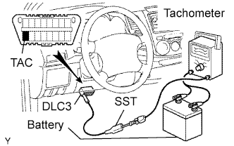
When not using the intelligent tester:
Check the ignition timing.
-
Using SST, connect tachometer probe to terminal TAC of the DLC3.
- SST
- 09843-18030
Note
-
Confirm the terminal numbers before connecting them. Connection with a wrong terminal can damage the engine.
-
Turn off all electrical systems before connecting the terminals.
-
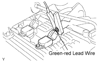
Clamp the tester probe of a timing light to the 4 lead wires or green-red lead wire of the ignition coil connector for No. 1 cylinder.
-
Start the engine.
-
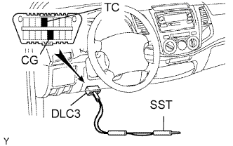
Using SST, connect terminals TC and CG of the DLC3.
- SST
- 09843-18040
Note
When checking the ignition timing, the transmission should be in the neutral position.
Tech Tips
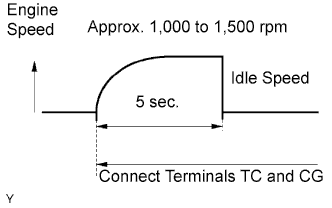
-
After connecting terminals (TC and CG), engine rpm changes to approximately 1,000 to 1,500 rpm for 5 seconds, then returns to idle speed. Because the ECM checks that the ISC (idle speed control system) operates properly.
-
Perform the inspection of the ignition timing after engine rpm is returned to idle speed.
-
Using a timing light, measure the ignition timing.
Standard ignition timing 3 to 7° BTDC @ idle -
Remove the SST from terminals 13 (TC) and 4 (CG) of the DLC3.
-
Check the ignition timing.
Standard ignition timing 0 to 20° BTDC @ idle -
Confirm that ignition timing moves to the advanced angle side when the engine speed is increased.
-
Remove the timing light.
-
-
-
CHECK IDLE SPEED
-
Warm up and stop the engine.
Note
A warmed up engine should have an engine coolant temperature of over 80°C (176°F), have an engine oil temperature of 60°C (140°F), and the engine rpm should be stabilized.
-
When using the intelligent tester:
Check the idle speed.
-
Connect the intelligent tester to the DLC3.
Tech Tips
Please refer to the intelligent tester II operator's manual for further details.
-
Start the engine at idle.
-
Turn the intelligent tester main switch ON.
-
Enter the following item: Powertrain / Engine and ECT / Data List / Engine SPD.
Standard idle speed 600 to 700 rpm Note
-
When checking the idle speed, the transmission should be in the neutral position.
-
Switch off all accessories and air conditioning before connecting the intelligent tester.
-
-
-
When not using the intelligent tester:
Check the idle speed.
-
Using SST, connect tachometer tester probe to terminal 9 (TAC) of the DLC3.
- SST
- 09843-18030
-
Start the engine at idle.
-
Check the idle speed.
Standard idle speed 600 to 700 rpm
-
-
-
CHECK CO/HC
-
Start and warm up the engine.
-
Run the engine at 2,500 rpm for approximately 180 seconds and idle the engine.
-
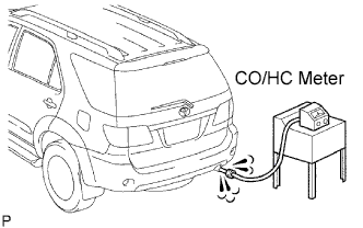
Insert CO/HC meter testing probe at least 40 cm (1.3 ft.) into the tailpipe.
-
Check CO/HC concentration at idle.
Idle CO concentration 0 to 0.5% Idle HC concentration Applicable local regulation -
If the CO/HC concentration is not as specified, perform troubleshooting in the order given below.
-
Check the heated oxygen sensor operation Click here.
-
See the table below for possible causes, and then inspect and repair the applicable causes if necessary.
CO HC Problems Causes Normal High Rough idle
-
Faulty ignitions:
-
Incorrect timing
-
Plugs are contaminated, shorted or gaps are defective
-
Incorrect valve clearance
-
Leaks in intake and exhaust valves
-
Leaks in cylinders
Low High Rough idle
(Fluctuating HC reading)
-
Vacuum leaks:
-
Ventilation hoses
-
Intake manifold
-
Throttle body
-
Brake booster line
-
Lean mixture causing misfire
High High Rough idle
(Black smoke from exhaust)
-
Restricted air filter
-
Plugged ventilation valve
-
Faulty SFI system:
-
Faulty pressure regulator
-
Defective ECT sensor
-
Defective Mass Air Flow (MAF) meter
-
Faulty ECM
-
Faulty injectors
-
Faulty throttle position sensor
-
-
-
-
CHECK FUNCTION OF THROTTLE BODY
-
Check the throttle control motor operating sound.
-
Turn the ignition switch ON.
-
When pressing the accelerator pedal, check the operating sound of the running motor. Make sure that no friction noises emit from the motor.
If friction noise is heard, replace the throttle body.
-
-
Check the throttle position sensor.
-
Connect the intelligent tester to the DLC3.
-
Turn the ignition switch ON.
-
Under Current Data, check that the throttle valve opening percentage (Throttle Pos) is within the standard.
Standard throttle valve opening percentage 60% or more Note
When checking the standard throttle valve opening percentage, the shift lever should be in the N position.
If the percentage is less than 60%, replace the throttle body.
-
-