CAMSHAFT REMOVAL

-
DISCONNECT CABLE FROM NEGATIVE BATTERY TERMINAL
CAUTION:
Wait at least 90 seconds after disconnecting the cable from the negative (-) battery terminal to prevent airbag activation.
-
REMOVE DRIVE BELT
-
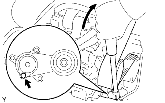
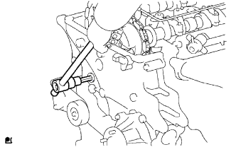
Use the hexagon-shaped part indicated by the arrow in the illustration to move the tensioner pulley downward and decrease the tension in the drive belt. Then remove the drive belt.
Note
When removing the drive belt, do not use the idle pulley's bolt.
Tech Tips
After removing the drive belt, move the tensioner upward to the maximum amount.
-
-
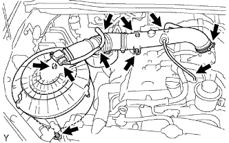
REMOVE INTAKE AIR CONNECTOR
-
Disconnect the vacuum hose.
-
Disconnect the No. 2 ventilation hose.
-
Disconnect the MAF meter connector and wire harness clamps.
-
Loosen the hose clamp and remove the 4 bolts, air cleaner and intake air connector assembly.
-
-
REMOVE IGNITION COIL
-
Remove the bolt and ignition coil.
-
-
REMOVE CYLINDER HEAD COVER
-
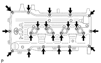
Disconnect the wire harness from the 6 clamps.
-
Remove the 19 bolts, 2 nuts, cylinder head cover and 2 gaskets.
-
-
REMOVE TIMING CHAIN GUIDE
-
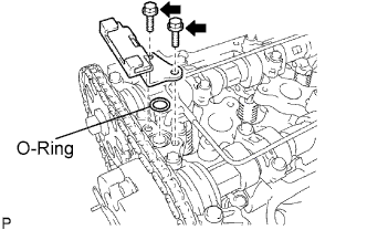
Remove the 2 bolts, chain guide and O-ring.
-
-
REMOVE CAMSHAFT TIMING SPROCKET
-

Turn the crankshaft pulley, and align its groove with timing mark 0 of the timing chain cover.
-
Check that the timing marks of the camshaft timing gear and sprocket are aligned with the timing marks of the No. 1 bearing cap, as shown in the illustration.
-
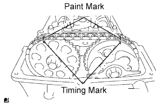
Place paint marks on the timing chain and camshaft timing gear/sprocket.
-
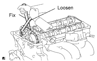
Fix the camshaft with a wrench and then loosen the sprocket bolt.
Note
Be careful not to damage the oil delivery pipe.
-
Using a 10 mm socket hexagon wrench, remove the timing chain cover plug.
-
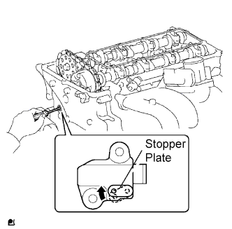
Using a screwdriver, access the tensioner stopper plate through the chain tensioner service hole. Move the stopper plate upward to release the lock. Then hold the plate in that position as shown in the illustration.
Tech Tips
If the stopper plate's lock is difficult to release, slightly rotate the camshaft's hexagon-shaped part to the left and right.
-
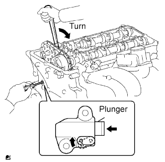
With the stopper plate's lock released, slightly rotate the camshaft to the right. Then maintain that position.
Note
Be careful not to damage the oil delivery pipe.
Tech Tips
Rotating the camshaft to the right will cause pressure to be applied to the tensioner plunger.
-
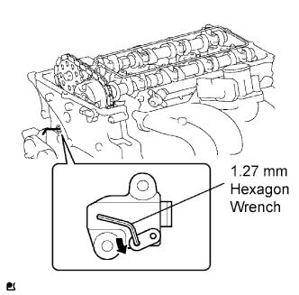
Remove the screwdriver from the chain tensioner service hole. Move the stopper plate to the position shown in the illustration. Then insert a hexagon wrench into the hole.
Tech Tips
-
If the wrench cannot fit into the hole, slightly rotate the camshaft to the left and then to the right. Then insert the wrench.
-
To prevent the wrench from falling out, use tape to fix the wrench in place.
-
-
Remove the camshaft timing sprocket from the camshaft.
-
-
REMOVE CAMSHAFT
-
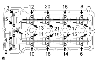
Uniformly loosen the 21 bearing cap bolts in several passes in the sequence shown in the illustration.
-
Remove the 9 bearing caps, oil delivery pipe, O-ring and camshaft.
Note
-
Place the camshaft on a flat surface, maintain this position and loosen the bolts uniformly.
-
Do not pry the camshaft with a tool by applying excessive force to it.
-
Do not damage the reception part of exhaust on the cylinder head side.
-
-
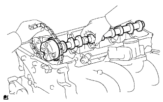
Remove the camshaft while holding the timing chain.
-
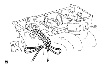
Tie the timing chain with a string as shown in the illustration.
Note
Be careful not to drop anything inside the timing chain cover.
-
-
REMOVE VALVE ROCKER ARM
Tech Tips
Each rocker arm must be reinstalled to its original location.
-
REMOVE VALVE LASH ADJUSTER
Tech Tips
Each lash adjuster must be reinstalled to its original location.
-
REMOVE CAMSHAFT TIMING GEAR
-
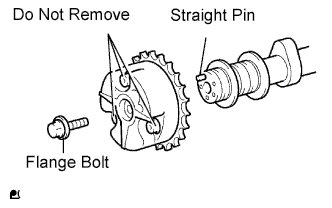
Remove the flange bolt of the camshaft timing gear.
Note
-
Be sure not to remove the other 3 bolts.
-
If planning to reuse the gear, be sure to release the straight pin lock before installing the gear.
-
-
-
REMOVE VALVE STEM CAP
Tech Tips
Each stem cap must be reinstalled to its original locations.