FUEL INJECTOR INSTALLATION

-
INSTALL INJECTOR ASSEMBLY

-
Install a new insulator to each fuel injector.
-
Apply a light coat of spindle oil or gasoline to a new O-ring and install it to each fuel injector.
-

While turning the fuel injector left and right, install it to the fuel delivery pipe.
-
Position the fuel injector connector outward.
-
-
INSTALL FUEL DELIVERY PIPE SUB-ASSEMBLY

-
Place the fuel delivery pipe together with the 6 fuel injectors on the intake manifold.
-
Temporarily install the 6 bolts which are used to hold the fuel delivery pipe to the intake manifold.
-
Check that the fuel injectors rotate smoothly.
Tech Tips
If the fuel injectors do not rotate smoothly, the probable cause is incorrect installation of the O-ring. Replace the O-ring.
-
Position the fuel injector connector outward.
-
Tighten the 6 bolts which are used to hold the fuel delivery pipe to the intake manifold.
- Torque:
- 15 N*m { 153 kgf*cm, 11 ft.*lbf }
-
Connect the 6 fuel injector connectors.
-
-
CONNECT NO. 2 FUEL PIPE SUB-ASSEMBLY
-
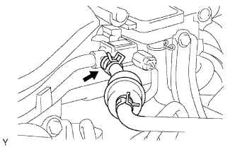
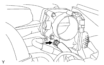
Connect the fuel pipe.
-
Check that there is no damage or contamination in the connected part of the pipe.
-
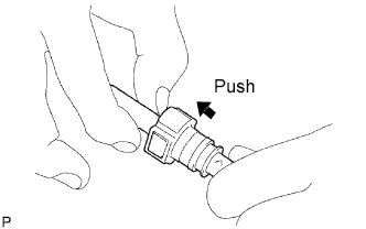
Align the axis of the connector with the axis of the pipe. Push the pipe into the connector until the connector makes a "click" sound. If the connection is tight, apply a small amount of fresh engine oil on the tip of the pipe.
-
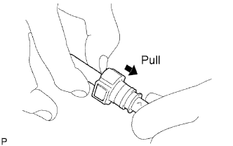
After completing the connection, try to pull apart the pipe and the connector and confirm that they are securely connected.
-
-
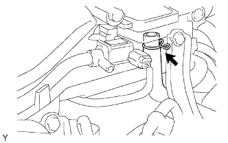
Install the fuel pipe clamp.
-
-
CONNECT NO. 1 FUEL PIPE SUB-ASSEMBLY
-
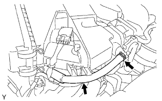
Connect the fuel pipe.
-
Check that there is no damage or contamination in the connected part of the pipe.
-
Align the axis of the connector with the axis of the pipe. Push the pipe into the connector until the connector makes a "click" sound. If the connection is tight, apply a small amount of fresh engine oil on the tip of the pipe.
-
After completing the connection, try to pull apart the pipe and the connector and confirm that they are securely connected.
-
-
Install the fuel pipe clamp.
-
-
INSTALL INTAKE AIR SURGE TANK
-
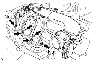
Install a new gasket and the surge tank with the 2 nuts.
- Torque:
- 28 N*m { 286 kgf*cm, 21 ft.*lbf }
-
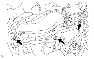
Using an 8 mm hexagon wrench, install the 4 bolts.
- Torque:
- 28 N*m { 286 kgf*cm, 21 ft.*lbf }
-
Install the 3 upper bolts which are used to secure the 2 surge tank stays and throttle body bracket.
- Torque:
- 21 N*m { 214 kgf*cm, 16 ft.*lbf }
-
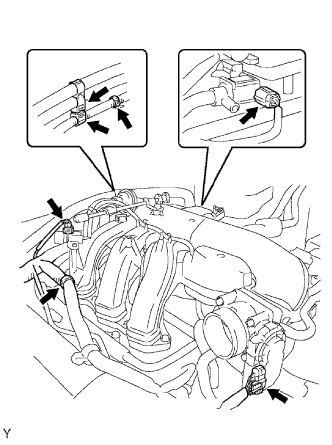
Install the 3 wire harness clamps and hose clamp.
-
Connect the throttle position sensor and control motor connector.
-
Connect the purge VSV connector.
-
Connect the VSV (for ACIS) connector.
-
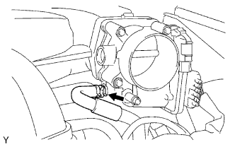
Connect the No. 1 ventilation hose.
-
Connect the purge line hose.
-
Connect the No. 4 water by-pass hose.
-
Connect the No. 5 water by-pass hose.
-
-
INSTALL AIR CLEANER ASSEMBLY
-
CONNECT NO. 2 VENTILATION HOSE
-
INSTALL V-BANK COVER
-
Install the cover with the 2 nuts.
- Torque:
- 7.5 N*m { 76 kgf*cm, 66 in.*lbf }
-
-
ADD ENGINE COOLANT
-
Tighten all the plugs and fill the radiator with TOYOTA Super Long Life Coolant (SLLC).
- Torque:
- 13 N*m { 130 kgf*cm, 9 ft.*lbf, for cylinder block drain cock plug }
Standard capacity Item Specified Condition A/T 9.8 liters (10.4 US qts, 8.6 Imp. qts) M/T 8.5 liters (9.0 US qts, 7.5 Imp. qts) Tech Tips
-
TOYOTA vehicles are filled with TOYOTA SLLC at the factory. In order to avoid damage to the engine cooling system and other technical problems, only use TOYOTA SLLC or similar high quality ethylene glycol based non-silicate, non-amine, non-nitrite, non-borate coolant with long-life hybrid organic acid technology (coolant with long-life hybrid organic acid technology consists of a combination of low phosphates and organic acids).
-
Please contact your TOYOTA dealer for further details.
Note
Never use water as a substitute for engine coolant.
-
Fill the radiator reservoir with TOYOTA Super Long Life Coolant (SLLC) to the F line.
-
Install the radiator cap.
-
Bleed air from the cooling system.
-
Warm up the engine until the thermostat opens.
While the thermostat is open, circulate the coolant for several minutes.
-
Maintain the engine speed at 2,500 to 3,000 rpm.
-
Press the inlet and outlet radiator hoses several times by hand to bleed air.
CAUTION:
When pressing the radiator hoses:
-
Wear protective gloves.
-
Be careful as the radiator hoses are hot.
-
Keep your hands away from the radiator fan.
-
-
-
Stop the engine and wait until the coolant cools down to ambient temperature.
CAUTION:
Do not remove the radiator cap while the engine and radiator are still hot. Pressurized, hot engine coolant and steam may be released and cause serious burns.
-
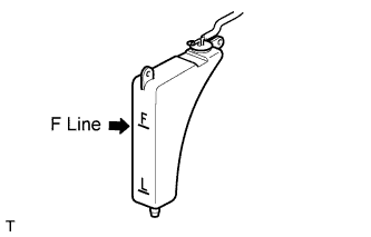
Check the coolant level in the radiator reservoir.
If the coolant level is below the L line, add SLLC to the reservoir F line.
-
-
CONNECT CABLE TO NEGATIVE BATTERY TERMINAL
-
PERFORM INITIALIZATION
-
Perform initialization Click here.
Note
Certain systems need to be initialized after disconnecting and reconnecting the cable from the negative (-) battery terminal.
-
-
CHECK FOR FUEL LEAKS
-
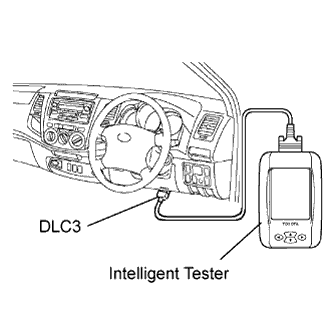
Connect the intelligent tester to the DLC3.
-
Turn the ignition switch ON.
Note
Do not start the engine.
-
Push the intelligent tester main switch ON.
-
To perform the Active Test, enter the following menus: Powertrain / Engine and ECT / Active Test / Control the Fuel Pump / Speed.
-
-
Check the fuel pump operation.
-
Check for pressure in the fuel inlet tube from the fuel line. Check that the sound of fuel flowing in the fuel tank can be heard.
If there is no sound, check the integration relay, fuel pump, ECM and wiring connector.
-
-
Check for fuel leaks.
-
Check that there are no fuel leaks after performing maintenance anywhere on the system.
If there are fuel leaks, repair or replace the leaking parts.
-
-