ENGINE UNIT REPAIR

-
REPAIR INTAKE VALVE SEAT
Note
Keep the lip free from foreign matter.
-
Apply a light coat of Prussian blue (or white lead) to the valve face.
-
Lightly press the valve face against the valve seat.
-
Check the valve seat according to the following procedures.
-
If blue appears 360° around the valve face, the valve face is concentric. If not, replace the valve.
-
If blue appears 360° around the valve seat, the guide and valve face are concentric. If not, resurface the valve seat.
-
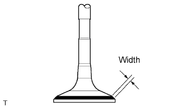
Check that the valve seat contact is in the middle of the valve face with the width between 1.0 to 1.4 mm (0.039 to 0.055 in.).
-
-
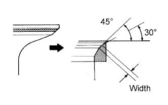
If the seating is too high on the valve face, use 30° and 45° cutters to correct the seat.
-
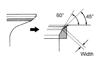
If the seating is too low on the valve face, use 60° and 45° cutters to correct the seat.
-
Hand-lap the valve and valve seat with an abrasive compound.
-
Check the valve seating position.
-
-
REPAIR EXHAUST VALVE SEAT
Note
Keep the lip free from foreign matter.
-
Apply a light coat of Prussian blue (or white lead) to the valve face.
-
Lightly press the valve face against the valve seat.
-
Check the valve seat according to the following procedures.
-
If blue appears 360° around the valve face, the valve face is concentric. If not, replace the valve.
-
If blue appears 360° around the valve seat, the guide and valve face are concentric. If not, resurface the valve seat.
-
Check that the valve seat contact is in the middle of the valve face with the width between 1.0 to 1.4 mm (0.039 to 0.055 in.).
-
-
If the seating is too high on the valve face, use 30° and 45° cutters to correct the seat.
-
If the seating is too low on the valve face, use 60° and 45° cutters to correct the seat.
-
Hand-lab the valve and valve seat with an abrasive compound.
-
Check the valve seating position.
-
-
BORE CYLINDER
Tech Tips
-
Bore all the 4 cylinders for the O/S piston outside diameter.
-
Replace all the piston rings with ones to match the O/S pistons.
-
Keep 4 new O/S pistons.
O/S 0.50 piston diameter 95.441 to 95.451 mm (3.7575 to 3.7579 in.) -
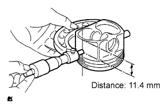
Using a micrometer, measure the piston diameter at right angles to the piston center line, the indicated distance from the piston end.
Standard distance 11.4 mm (0.449 in.) -
Calculate how much each cylinder needs to be rebored:
Size to be rebored = P + C - H P = Piston diameter C = Piston clearance: 0.019 to 0.052 mm (0.0007 to 0.0020 in.) H = Allowance for honing: 0.02 mm (0.0008 in.) or less -
Bore and hone the cylinders to calculated dimensions.
Maximum honing 0.02 mm (0.0008 in.) Note
Excess honing will destroy the finished roundness.
-