ENGINE UNIT REASSEMBLY

-
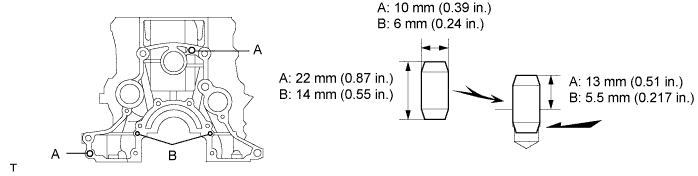
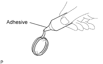
INSTALL TIGHT PLUG
-

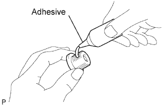
Apply adhesive around the tight plugs.
Adhesive Toyota Genuine Adhesive 1324, Three Bond 1324 or equivalent -
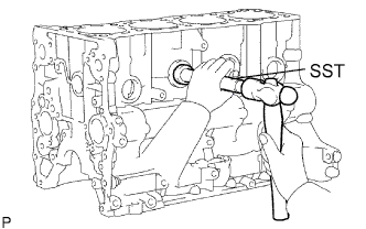
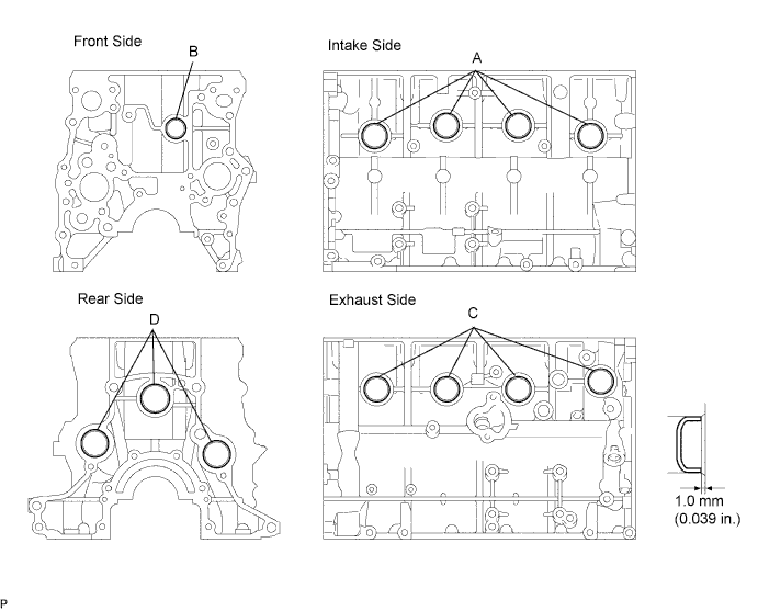
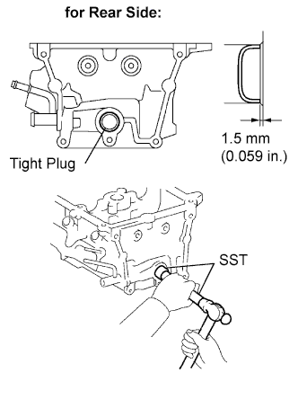
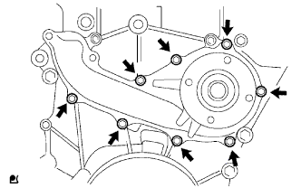
Using SST and a hammer, tap in new tight plugs as shown in the illustration.
-
Using SST, tap in the 8 tight plugs A and C.
- SST
- 09950-60010 ( 09951-00300 )
- 09950-70010 ( 09951-07100, 09951-00350, 09951-00400 )
-
Using SST, tap in the tight plug B.
- SST
- 09950-60010 ( 09951-00300 )
- 09950-70010 ( 09951-07100, 09951-00350, 09951-00400 )
-
Using SST, tap in the 3 tight plugs D.
- SST
- 09950-60010 ( 09951-00300 )
- 09950-70010 ( 09951-07100, 09951-00350, 09951-00400 )
-
-
-
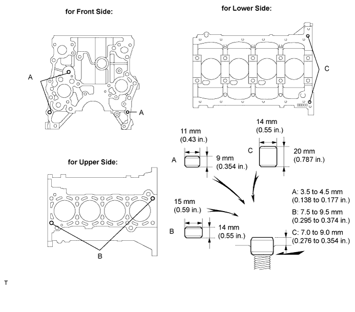
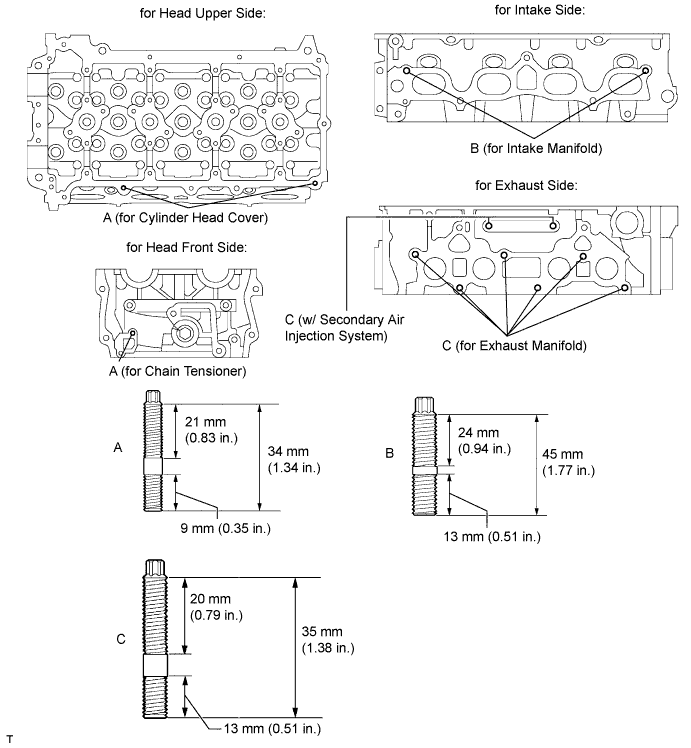
INSTALL STUD BOLT
-
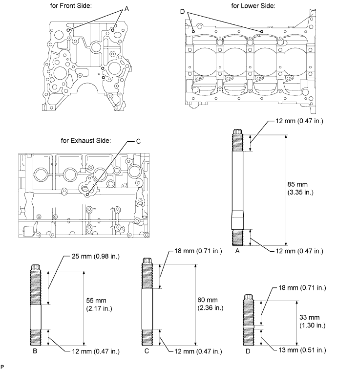
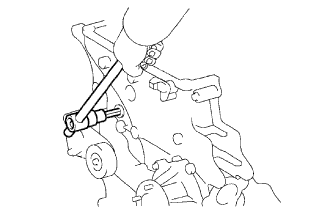
Using an E7 "TORX" socket wrench, install the stud bolts B and D.
- Torque:
- 7.5 N*m { 77 kgf*cm, 66 in.*lbf, for stud bolt B and D }
-
Using an E8 "TORX" socket wrench, install the stud bolts A.
- Torque:
- 7.5 N*m { 77 kgf*cm, 66 in.*lbf, for stud bolt A }
-
Apply adhesive to the hole for the stud bolt C on the cylinder block. Using an E7 "TORX" socket wrench, install the stud bolt C.
- Torque:
- 7.5 N*m { 77 kgf*cm, 66 in.*lbf, for stud bolt C }
Note
If the stud bolt is deformed or the threads are damaged, replace it.
-
-
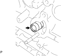
INSTALL STRAIGHT PIN
-
Using a plastic-faced hammer, tap in new straight pins to the cylinder block.
-
-
INSTALL RING PIN
-
Using a plastic-faced hammer, tap in new ring pins to the cylinder block.
-
-
INSTALL NO. 2 BALANCE SHAFT DRIVEN GEAR
-
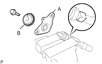
Mount the head portion of the balance shaft in a vise.
Note
Be careful not to damage the balance shaft.
-
Install the No. 2 balance shaft thrust washer (labeled A) and balance shaft No. 2 driven gear (labeled B).
-
Install and torque the bolt.
- Torque:
- 36 N*m { 367 kgf*cm, 27 ft.*lbf }
-
-
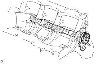
INSTALL NO. 2 BALANCE SHAFT
-
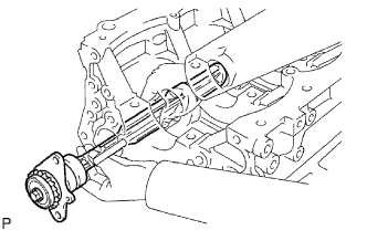
Install the balance shaft to the cylinder block.
Note
When installing the balance shaft, make sure to support the balance shaft with both hands and avoid scratching the balance shaft bearing on the cylinder block side.
-
Install the 2 bolts.
- Torque:
- 18 N*m { 184 kgf*cm, 13 ft.*lbf }
-
-
INSTALL NO. 1 BALANCE SHAFT DRIVEN GEAR
-
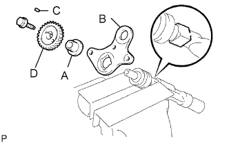
Mount the head portion of the balance shaft in a vise.
Note
Be careful not to damage the balance shaft.
-
Install the balance shaft thrust spacer (labeled A), No. 1 balance shaft thrust washer (labeled B), sliding key (labeled C) and No. 1 balance shaft driven gear (labeled D).
-
Install the bolt.
- Torque:
- 36 N*m { 367 kgf*cm, 27 ft.*lbf }
-
-
INSTALL NO. 1 BALANCE SHAFT
-
Install the No. 1 balance shaft to the cylinder block.
Note
When installing the balance shaft, make sure to support the balance shaft with both hands and avoid scratching the balance shaft bearing on the cylinder block side.
-
Install and torque the bolt.
- Torque:
- 18 N*m { 184 kgf*cm, 13 ft.*lbf }
-
-
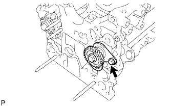
CHECK BALANCE SHAFT THRUST CLEARANCE
-
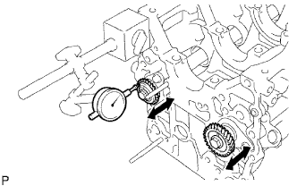
Using a dial indicator, measure the thrust clearance while moving the balance shaft back and forth.
Standard thrust clearance 0.07 to 0.13 mm (0.0027 to 0.0051 in.) Maximum thrust clearance 0.20 mm (0.0079 in) If the thrust clearance is greater than the maximum, replace the balance shaft thrust washer. If necessary, replace the balance shaft.
-
-
INSTALL OIL NOZZLE
-
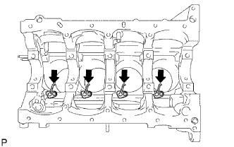
Using an E7 "TORX" socket wrench, install the oil nozzle.
- Torque:
- 7.0 N*m { 71 kgf*cm, 62 in.*lbf }
-
-
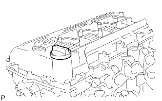
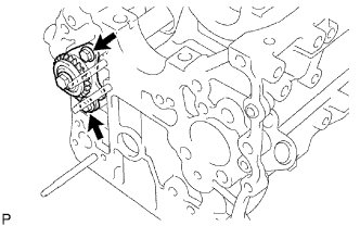
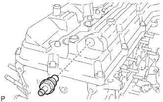
INSTALL CYLINDER BLOCK WATER DRAIN COCK
-
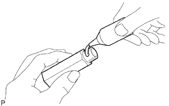
Apply adhesive around the drain cock.
Adhesive Toyota Genuine Adhesive 1324, Three Bond 1324 or equivalent -
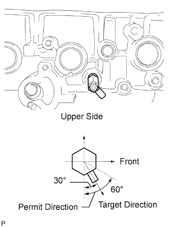
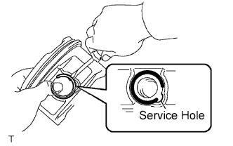
Install the cylinder block water drain cock as shown in the illustration.
- Torque:
- 19.6 N*m { 200 kgf*cm, 15 ft.*lbf }
-
Install the water drain cock plug to the water drain cock.
- Torque:
- 13 N*m { 130 kgf*cm, 9 ft.*lbf }
-
-
INSTALL PISTON WITH PIN
-
Assemble the piston and connecting rod.
-
Using a small screwdriver, install a new snap ring at one end of the piston pin hole.
-
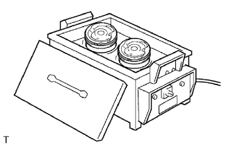
Gradually heat the piston to approximately 80 to 90°C (176 to 194°F).
-
Coat the piston pin with engine oil.
-
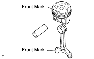
Align the front marks of the piston and connecting rod, and push in the piston pin with your thumb.
Tech Tips
The piston and pin are a matched set.
-
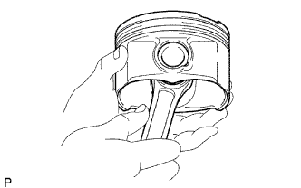
Check the fit between the piston and piston pin by trying to move the piston back and forth on the piston pin.
-
Using a small screwdriver, install a new snap ring at the other end of the piston pin hole.
-
-
Install the piston rings.
-
Install the oil ring expander and 2 side rails by hand.
-
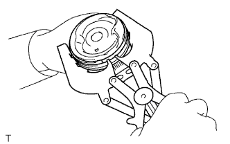
Using a piston ring expander, install the 2 compression rings with the painted mark as shown in the illustration.
Tech Tips
-
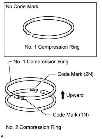
The No. 1 compression ring is reversible.
-
There are 2 types of No. 1 compression rings. One type has a code mark and the other does not.
-
Install the No. 1 compression ring with the code mark (1N) facing upward.
-
Install the No. 2 compression ring with the code mark (2N) facing upward.
-
-
-
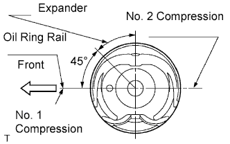
Position the piston rings so that the ring ends are as shown in the illustration.
Note
Do not align the ring ends.
-
-
INSTALL CONNECTING ROD BEARING
-
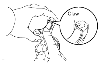
Align the bearing claw with the groove of the connecting rod or connecting cap.
-
Install the bearings in the connecting rod and connecting rod cap.
Note
Clean the backside of the bearing and the bearing surface of the connecting rod. The surface should be free of dust and oil.
-
-
INSTALL CRANKSHAFT BEARING
Note
Do not apply engine oil to the bearing's contact area and backside.
-
Clean the main journal, and the interior and exterior of the bearing.
-
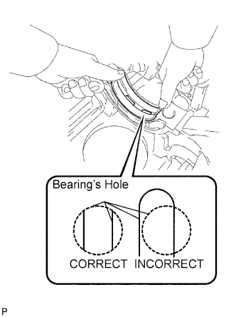
Install the upper bearing.
-
Install the upper bearing to the cylinder block so that the upper bearing's lubrication hole is centered within the cylinder block's lubrication hole, as shown in the illustration.
Reference (Difference in dimension of cylinder block and upper bearing) Item Specified Condition # 1, 5 journal 3.75 mm (0.1476 in.) # 3 journal 1.75 mm (0.0689 in.) # 2, 4 journal 2.75 mm (0.1083 in.) Note
Do not apply engine oil to the bearing's contact area and backside.
-
-
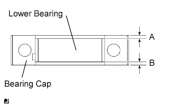
Install the lower bearing.
-
Install the lower bearing to the bearing cap.
-
Using a vernier caliper, measure the distance between the bearing cap's edge and the lower bearing's edge.
Standard dimension (A - B) 0.3 mm (0.0118 in.) or less Reference: (Dimension of A or B) Item Specified Condition # 1, 5 journal 3.83 mm (0.1508 in.) # 3 journal 1.74 mm (0.0685 in.) # 2, 4 journal 2.75 mm (0.1083 in.) Note
Do not apply engine oil to the bearing's contact area and backside.
-
-
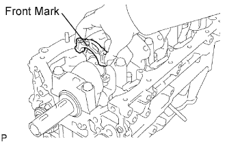
With the upper bearing and lower bearing installed, use a plastic-faced hammer to install the bearing caps to the cylinder block.
Note
Make sure the bearing cap's front mark and journal number are correct.
-
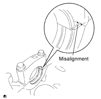
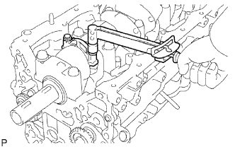
Using a vernier caliper, measure the amount of misalignment between the upper bearing and lower bearing, as shown in the illustration.
Standard value 0.9 mm (0.035 in.) or less -
Remove the bearing cap.
-
-
INSTALL CRANKSHAFT
Note
The crankshaft bearing cap bolt is tightened in 2 progressive steps.
-
Install the crankshaft thrust washer upper to the cylinder block.
-
Install the 2 thrust washers under the No. 3 journal position of the cylinder block with the oil grooves facing outward.
Note
Be careful when installing the thrust bearing upper and lower as they are similar but cannot be interchanged.
-
-
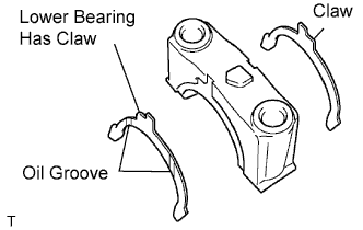
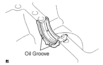
Install the 2 thrust washers on the No. 3 bearing cap with the grooves facing outward.
Note
Be careful when installing the thrust bearing upper and lower as they are similar but cannot be interchanged. The lower bearing has a claw as shown in the illustration.
-
Apply engine oil to the upper bearing, then place the crankshaft on the cylinder block.
-
Apply engine oil to the lower bearing.
-
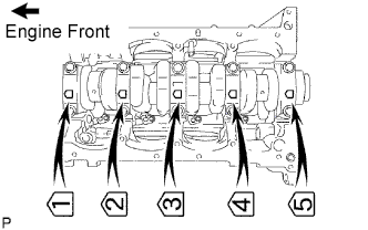
Install the 5 crankshaft bearing caps in their proper locations.
-
Install the crankshaft bearing cap bolts.
Tech Tips
-
The main bearing cap bolts are tightened in 2 progressive steps.
-
If any of the main bearing cap bolts are broken or deformed, replace as necessary.
-
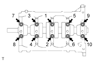
Install and uniformly tighten the 10 main bearing cap bolts in the sequence shown in the illustration.
- Torque:
- 39 N*m { 398 kgf*cm, 29 ft.*lbf }
If any one of the main bearing cap bolts does not meet the torque specification, replace the main bearing cap bolt.
-
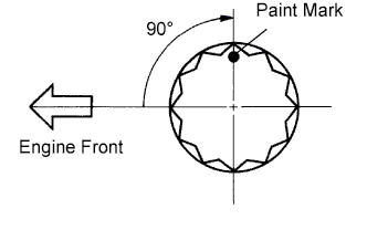
Mark the front of the bearing cap bolts with paint.
-
Retighten the bearing cap bolts by 90° in the numerical order above.
-
Check that the painted mark is now at a 90° angle to the front.
-
-
Check that the crankshaft turns smoothly.
-
-
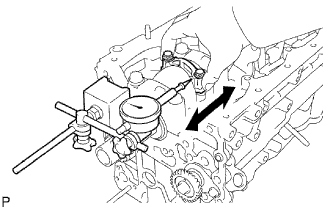
CHECK CRANKSHAFT THRUST CLEARANCE
-
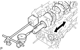
Using a dial indicator, measure the thrust clearance while prying the crankshaft back and forth with a screwdriver.
Standard thrust clearance 0.020 to 0.220 mm (0.0008 to 0.0087 in.) Maximum thrust clearance 0.30 mm (0.0118 in.) If the thrust clearance is greater than the maximum, replace the thrust washers as a set.
Thrust washer thickness 2.440 to 2.490 mm (0.0961 to 0.0980 in.)
-
-
INSTALL PISTON WITH CONNECTING ROD
-
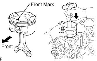
Using a piston ring compressor, push the correctly numbered piston and connecting rod assembly into the cylinder with the front mark of the piston facing forward.
-
Match the numbered connecting rod cap with the connecting rod.
-
Align the pins of the connecting rod cap with the pin holes of the connecting rod, and install the connecting rod cap.
-
Check that the front mark of the connecting rod cap is facing forward.
-
-
Install the connecting rod cap bolts.
Tech Tips
-
The connecting rod cap bolts are tightened in 2 progressive steps.
-
If any connecting rod bolt is broken or deformed, replace it.
-
Apply a light coat of engine oil on the threads and under the heads of the connecting rod cap bolts.
-
Install and alternately tighten the bolts of the connecting rod cap in several passes.
- Torque:
- 24.5 N*m { 250 kgf*cm, 18 ft.*lbf }
If any one of the connecting rod cap bolts does not meet the torque specification, replace the cap bolts.
-
Mark the front of the connecting rod cap bolts with paint.
-
Retighten the connecting rod cap bolts 90° as shown.
-
Check that the painted mark is now at a 90° angle to the front.
-
-
Check that the crankshaft turns smoothly.
-
-
CHECK CONNECTING ROD THRUST CLEARANCE
-
Using a dial indicator, measure the thrust clearance while moving the connecting rod back and forth.
Standard thrust clearance 0.15 to 0.35 mm (0.006 to 0.014 in.) Maximum thrust clearance 0.40 mm (0.016 in.) If the thrust clearance is greater than the maximum, replace the connecting rod assembly(s). If necessary, replace the crankshaft.
-
-
INSTALL RING PIN
-
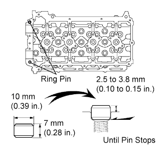
Using a plastic-faced hammer, tap in a new ring pin until the pin stops.
-
-
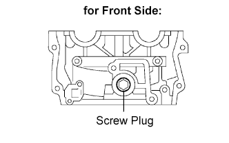
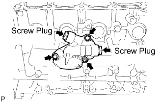
INSTALL NO. 1 STRAIGHT SCREW PLUG
-
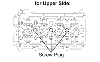
Using a 10 mm hexagon wrench, install a new gasket and the straight screw plug.
- Torque:
- 44 N*m { 449 kgf*cm, 32 ft.*lbf }
-
-
INSTALL NO. 2 STRAIGHT SCREW PLUG
-
Using a 19 mm hexagon wrench, install a new gasket and the straight screw plug.
- Torque:
- 140 N*m { 1428 kgf*cm, 103 ft.*lbf }
-
-
INSTALL TIGHT PLUG
-
Apply adhesive to the tight plug hole of the cylinder head.
Adhesive Toyota Genuine Adhesive 1324, Three Bond 1324 or equivalent -
Using SST and a hammer, tap in a new tight plug to the cylinder head as shown in the illustration.
- SST
- 09950-60010 ( 09951-00250 )
- 09950-70010 ( 09951-07100 )
-
-
INSTALL STUD BOLT
-
Using E5 and E7 "TORX" socket wrenches, install the stud bolts.
- Torque:
- 3.0 N*m { 31 kgf*cm, 27 in.*lbf, for stud bolt A }
- 7.5 N*m { 76 kgf*cm, 66 in.*lbf, for stud bolt B and C }
-
-
INSTALL OIL CONTROL VALVE FILTER
-
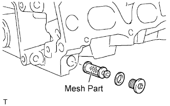
Check that no foreign matter is on the mesh part of the filter.
If foreign objects are present, clean the part thoroughly.
-
Using a 6 mm hexagon wrench, install a new gasket and the oil control valve filter with the screw plug.
- Torque:
- 30 N*m { 306 kgf*cm, 22 ft.*lbf }
-
-
INSTALL VALVE SPRING SEAT
-
INSTALL VALVE STEM OIL SEAL
-
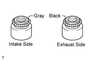
Apply a light coat of engine oil on a new oil seal.
Note
Pay close attention when installing the intake and exhaust oil seals. For example, installing the intake oil seal into the exhaust or installing the exhaust oil seal to the intake can cause installation problems later.
Tech Tips
The intake valve oil seal is gray and the exhaust valve oil seal is black.
-

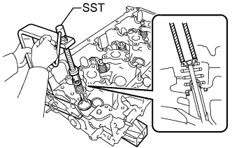
Using SST, push in the oil seal.
- SST
- 09201-41020
Note
Failure to use SST will cause the seal to be damaged or improperly seated.
-
-
INSTALL INTAKE VALVE
-
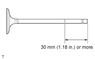
Apply plenty of engine oil to the tip area of the intake valve indicated in the illustration.
-
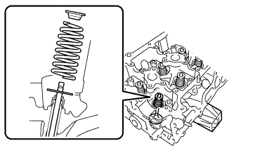
Install the valve, spring seat, compression spring and spring retainer to the cylinder head.
Note
Install the same parts in the same combination to the original locations.
-
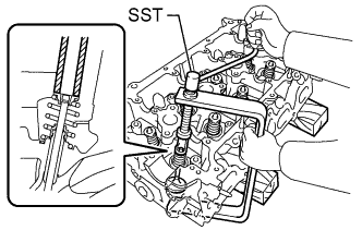
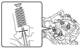
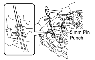
Using SST and wooden blocks, compress the spring and install the 2 retainer locks.
- SST
- 09202-70020
- 09202-00020
-
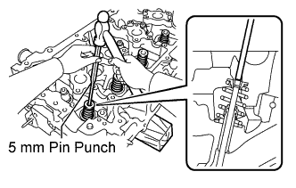
Using a 5 mm pin punch and plastic-faced hammer, lightly tap the valve stem tip to ensure a proper fit.
Note
Be careful not to damage the valve stem tip.
-
-
INSTALL EXHAUST VALVE
-
Apply plenty of engine oil to the tip area of the exhaust valve indicated in the illustration.
-
Install the valve, spring seat, compression spring and spring retainer to the cylinder head.
Note
Install the same parts in the same combination to the original locations.
-
Using SST and wooden blocks, compress the spring and install the 2 retainer locks.
- SST
- 09202-70020
- 09202-00020
-
Using a 5 mm pin punch and plastic-faced hammer, lightly tap the valve stem tip to ensure a proper fit.
Note
Be careful not to damage the valve stem tip.
-
-
INSTALL VALVE LASH ADJUSTER
Note
-
Keep the lash adjuster free from dirt and foreign objects.
-
Only use clean engine oil.
-
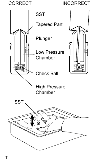
Place the lash adjuster into a container full of engine oil.
-
Insert SST's tip into the lash adjuster's plunger and use the tip to press down on the checkball inside the plunger.
- SST
- 09276-75010
-
Squeeze the SST and lash adjuster together to move the plunger up and down 5 to 6 times.
-
Check the movement of the plunger and bleed air.
OK Plunger moves up and down. Note
When bleeding high-pressure air from the compression chamber, make sure that the tip of the SST is actually pressing the checkball as shown in the illustration. If the checkball is not pressed, air will not bleed.
-
After bleeding air, remove SST. Then, try to quickly and firmly press the plunger with a finger.
OK Plunger is very difficult to move. If the result is not as specified, replace the lash adjuster.
Note
Install the lash adjuster to the same place it was removed from.
-
-
INSTALL VALVE STEM CAP
-
Apply a light coat of engine oil to the valve stem cap.
-
Install the valve stem cap to the cylinder head.
-
-
INSTALL VALVE ROCKER ARM
-
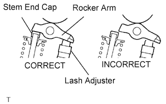
Apply clean engine oil to the valve lash adjuster tip and valve stem cap surface. Then install the valve rocker arm.
Note
Install the valve stem cap, lash adjuster and valve rocker arm to the same place it was removed from.
-
-
INSTALL CRANKSHAFT PULLEY SET KEY
-
Install the 2 pulley keys to the crankshaft.
-
-
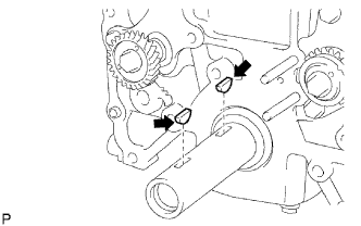
INSTALL NO. 4 CHAIN VIBRATION DAMPER
-
Install the No. 4 vibration damper with the 2 bolts.
- Torque:
- 18 N*m { 184 kgf*cm, 13 ft.*lbf }
-
-
INSTALL NO. 2 CHAIN
Note
Check that the No. 1 cylinder is at TDC and that the weights of the No. 1 and No. 2 balance shafts are at the bottom side.
-
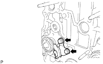
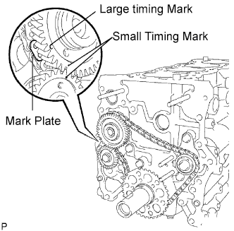
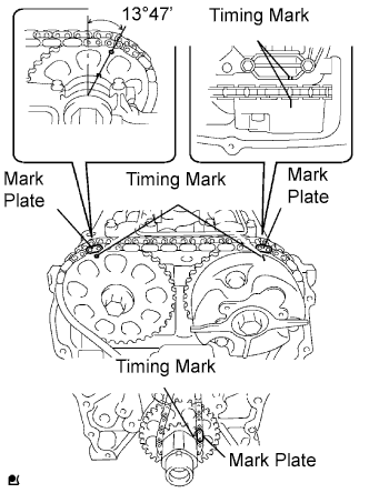
Install the No. 2 timing sprocket as shown in the illustration.
Tech Tips
Install the sprocket with the front mark facing forward.
-
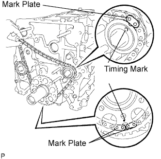
As shown in the illustration, install the chain on the sprocket and gear with the mark plates aligned with the timing marks on the sprocket and gear.
-
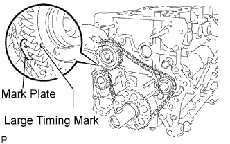
Fit the other mark plate of the balance shaft drive gear behind the large timing mark of the balance shaft drive gear.
-
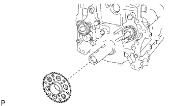
Insert the balance shaft drive gear shaft through the balance shaft drive gear so that it fits into the thrust plate hole.
-
Align the small timing mark of the balance shaft drive gear with the timing mark of the balance shaft timing gear.
-
Install the bolt to the balance shaft drive gear and tighten it.
- Torque:
- 25 N*m { 255 kgf*cm, 18 ft.*lbf }
-
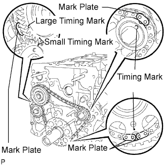
Check that each timing mark is matched with the corresponding mark plate.
Note
Check that the No. 1 cylinder is at TDC and that the weights of the No. 1 and No. 2 balance shafts are at the bottom side.
-
-
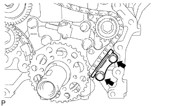
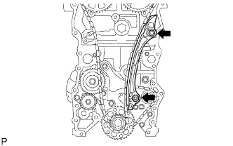
INSTALL NO. 2 CHAIN TENSIONER
-
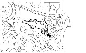
Install the No. 2 chain tensioner with the nut.
- Torque:
- 18 N*m { 184 kgf*cm, 13 ft.*lbf }
Note
Assemble the chain tensioner with the pin installed, then remove the pin after assembly. When doing this, avoid pushing the vibration damper against the chain.
-
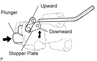
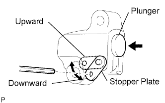
Move the stopper plate downward to release the lock, and push the plunger deep into the tensioner.
-
Move the stopper plate upward to set the lock, and insert a hexagon wrench into the stopper plate's hole.
-
-
INSTALL NO. 3 CHAIN VIBRATION DAMPER
-
Install the No. 3 chain vibration damper with the 2 bolts.
- Torque:
- 18 N*m { 184 kgf*cm, 13 ft.*lbf }
-
-
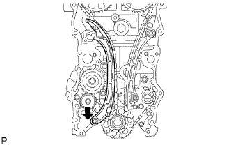
INSTALL NO. 2 CHAIN VIBRATION DAMPER
-
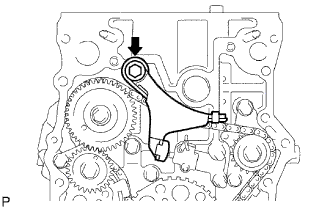
Install the No. 2 chain vibration damper with the bolt.
- Torque:
- 27 N*m { 270 kgf*cm, 20 ft.*lbf }
-
Remove the hexagon wrench from the No. 2 chain tensioner and release the plunger.
-
-
INSTALL ENGINE REAR OIL SEAL RETAINER
-
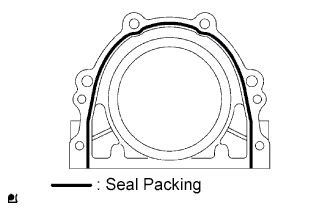
Apply seal packing in a continuous line to the places shown in the illustration.
Seal packing Toyota Genuine Seal Packing Black, Three Bond 1207B or equivalent Standard seal diameter 2 to 3 mm (0.079 to 0.118 in.) Note
-
Remove any oil from the contact surface.
-
Install the crankcase within 3 minutes after applying seal packing.
-
Do not start the engine for at least 2 hours after installing.
-
-
Install the oil seal retainer with the 6 bolts.
- Torque:
- 13 N*m { 133 kgf*cm, 10 ft.*lbf }
-
-
INSTALL OIL FILTER BRACKET
-
Using a 14 mm hexagon wrench, install the oil filter bracket union.
-
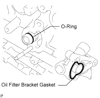
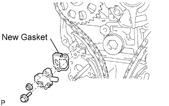
Install a new gasket to the oil filter bracket.
Note
Apply a light coat of engine oil to the new gasket.
-
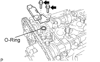
Install a new O-ring and gasket to the oil filter bracket union bolt.
Note
Apply a light coat of engine oil to the new O-ring.
-
Install the oil filter bracket with the 2 bolts and nut.
- Torque:
- 25 N*m { 255 kgf*cm, 18 ft.*lbf }
-
Install 2 new gaskets and 2 screws to the oil filter bracket.
- Torque:
- 49 N*m { 500 kgf*cm, 36 ft.*lbf }
-
-
INSTALL OIL FILTER UNION
-
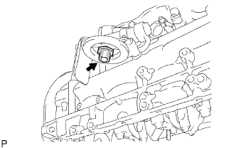
Using a 27 mm socket wrench, install the oil filter union.
- Torque:
- 43 N*m { 438 kgf*cm, 32 ft.*lbf }
-
-
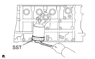
INSTALL OIL FILTER
-
Check and clean the oil filter installation surface.
-
Apply clean engine oil to the gasket of a new oil filter.
-
Lightly screw the oil filter into place, and tighten it until the gasket contacts the seat.
-
Using SST, tighten the oil filter.
- SST
- 09228-07501
-
When using a torque wrench:
Using a torque wrench to tighten the oil filter.
- Torque:
- 17.2 N*m { 175 kgf*cm, 13 ft.*lbf }
-
When not using a torque wrench:
Tighten the oil filter a 3/4 turn by a common wrench.
-
-
INSTALL CYLINDER HEAD GASKET
-
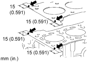
Apply seal packing to the cylinder block upper side and cylinder head gasket upper side as shown in the illustration.
Seal packing Toyota Genuine Seal Packing 1282B, Three Bond 1282B or equivalent Standard seal diameter 4 to 7 mm (0.15 to 0.28 in.) Note
-
Remove any oil from the contact surface.
-
Install the cylinder head gasket within 3 minutes after applying the seal packing.
-
Install the cylinder head bolt within 15 minutes after applying the seal packing.
-
Do not put into engine oil within 4 hours of installation.
-
-
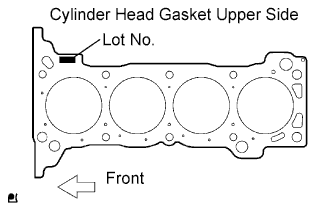
Place a new cylinder head gasket on the cylinder block surface with the Lot No. stamp upward.
Note
-
Make sure the installation direction is correct.
-
Place the cylinder head gently to avoid damaging the gasket with the bottom part of the head.
-
-
-
INSTALL CYLINDER HEAD
Tech Tips
The cylinder head bolts are tightened in 3 progressive steps.
-
Place the cylinder head on the cylinder block.
-
Apply a light coat of engine oil on the threads and under the heads of the cylinder head bolts.
-
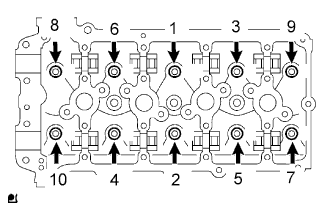
Using a 10 mm bi-hexagon wrench, install and uniformly tighten the 10 cylinder head bolts with the plate washers, in several passes, in the sequence shown.
- Torque:
- 39 N*m { 398 kgf*cm, 29 ft.*lbf }
-
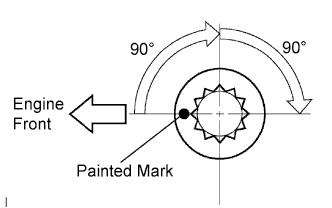
Mark the front of the cylinder head bolt head with paint.
-
Retighten the cylinder head bolts by 90° in the numerical order shown.
-
Retighten the cylinder head bolts by an additional 90°.
-
Check that the painted mark is now facing rearward.
-
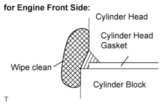
Seal packing will seep out on the engine's front side. Thoroughly wipe clean any seal packing.
-
-
INSTALL CAMSHAFT TIMING GEAR
-
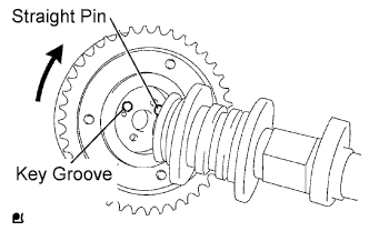
Put the camshaft timing gear and camshaft together by aligning the key groove and straight pin.
-
Check that there is no gap between the gear's flange and the camshaft.
- Torque:
- 78 N*m { 795 kgf*cm, 58 ft.*lbf }
-
With the camshaft timing gear fixed in place, tighten the flange bolt.
-
-
INSTALL CAMSHAFT TIMING SPROCKET
-
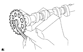
Clamp the camshaft in a vise and then install the camshaft timing sprocket to the camshaft with the sprocket bolt.
- Torque:
- 78 N*m { 795 kgf*cm, 58 ft.*lbf }
Note
Be careful not to damage the camshaft in the vise.
-
-
INSTALL CAMSHAFT
-
Apply clean engine oil to the camshaft's cam portion and the cylinder head journals.
-
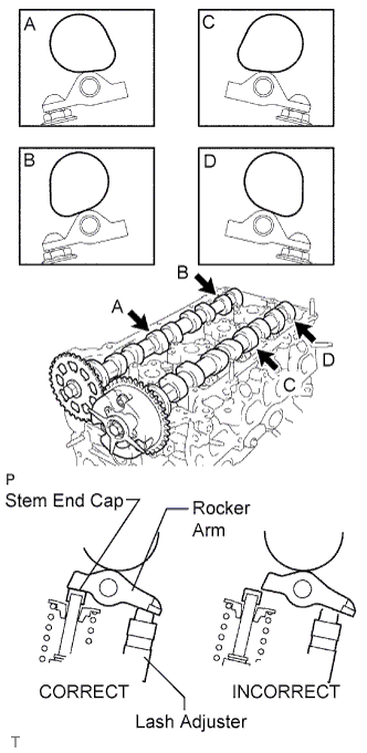
Set the camshaft and No. 2 camshaft as shown in the illustration.
Note
Before and after setting the camshaft and No. 2 camshaft, firmly set the rocker arm to the lash adjuster.
-
Loosely install the No. 1 camshaft bearing cap.
-
Check the proper location of each No. 2 camshaft bearing cap and install each one.
-
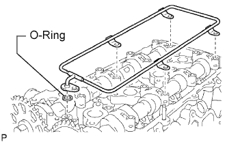
Install a new O-ring to the No. 1 camshaft bearing cap.
-
Loosely install the oil delivery pipe.
-
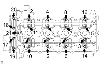
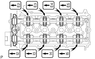
Tighten the 21 bolts and 20 washers in the order shown in the illustration.
- Torque:
- 12 N*m { 122 kgf*cm, 9 ft.*lbf, for bolt A }
- 15.5 N*m { 158 kgf*cm, 11 ft.*lbf, for except bolt A }
-
-
INSTALL CRANKSHAFT TIMING SPROCKET
-
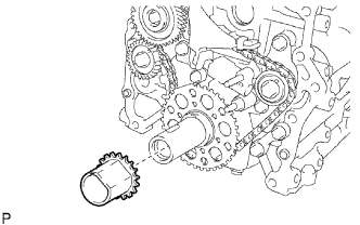
Install the timing sprocket as shown in the illustration.
-
-
INSTALL CHAIN VIBRATION DAMPER
-
Install the vibration damper with the bolt and nut.
- Torque:
- 21 N*m { 214 kgf*cm, 15 ft.*lbf }
-
-
INSTALL CHAIN
-
As shown in the illustration, install the chain on the sprocket and gear with the painted marks aligned with the timing marks on the sprocket and gear.
Tech Tips
-
The camshaft mark plate is yellow.
-
The crankshaft mark plate is orange.
-
-
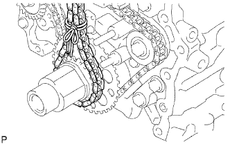
Use a rope to tie the chain of the crankshaft timing sprocket. Tie the rope near the sprocket.
Note
After the chain tensioner has been installed, the rope must be removed.
Tech Tips
The rope is tied so that the chain will not jump a tooth.
-
-
INSTALL CHAIN TENSIONER SLIPPER
-
Install the tensioner slipper with the bolt.
- Torque:
- 21 N*m { 214 kgf*cm, 15 ft.*lbf }
-
-
INSTALL CHAIN TENSIONER
-
Move the stopper plate upward to release the lock, and push the plunger deep into the tensioner.
-
Move the stopper plate downward to set the lock, and insert a 1.27 mm hexagon wrench into the stopper plate's hole.
-
Install a new gasket and the chain tensioner with the bolt and nut.
- Torque:
- 10 N*m { 102 kgf*cm, 7 ft.*lbf }
-
Remove the hexagon wrench.
-
-
INSTALL TIMING CHAIN GUIDE
-
Install a new O-ring and the chain guide with the 2 bolts.
- Torque:
- 10 N*m { 102 kgf*cm, 7 ft.*lbf }
-
-
INSTALL OIL PUMP RELIEF VALVE
-
Coat the relief valve with engine oil.
-
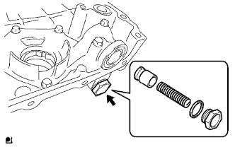
Install the relief valve and spring into the pump body hole.
-
Install a new gasket to the plug.
-
Using a 27 mm socket wrench, install the plug.
- Torque:
- 49 N*m { 500 kgf*cm, 36 ft.*lbf }
-
-
INSTALL WATER PUMP
-
Install a new gasket and the water pump with the 8 bolts.
- Torque:
- 13 N*m { 133 kgf*cm, 10 ft.*lbf }
-
-
INSTALL TIMING CHAIN COVER OIL SEAL
-
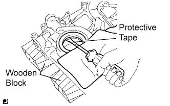
Place the timing chain cover on wooden blocks.
-
Using a screwdriver with its tip taped, pry out the oil seal.
-
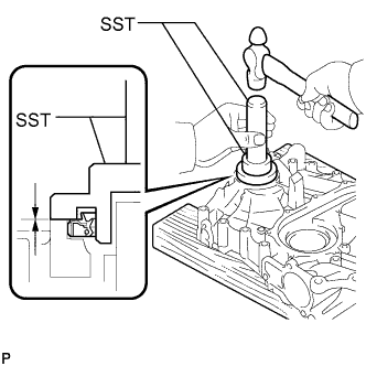
Using SST and a hammer, tap in a new oil seal until its surface is flush with the timing chain cover edge.
- SST
- 09223-75010
- 09950-70010 ( 09951-07150 )
Note
-
Keep the lip free from foreign matter.
-
Do not tap the oil seal at an angle.
Tech Tips
When installing the crankshaft pulley, check the shape of the pulley. The correct pulley has a groove Click here.
-
Apply a light coat of MP grease to a new oil seal lip.
-
-
INSTALL TIMING CHAIN COVER
-
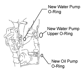
Install 3 new O-rings to the timing chain cover as shown in the illustration.
-
Apply adhesive to the timing gear case plug.
Adhesive Toyota Genuine Adhesive 1324, Three Bond 1324 or equivalent -
Using a 10 mm socket hexagon wrench, install the timing gear case plug.
- Torque:
- 16.6 N*m { 169 kgf*cm, 12 ft.*lbf }
-
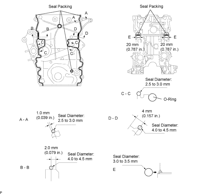
Apply seal packing in a continuous line as shown in the illustration.
Seal packing Toyota Genuine Seal Packing Black, Three Bond 1207B or equivalent Standard seal diameter Position Specified Condition A - A, C - C 2.5 to 3.0mm (0.098 to 0.118 in.) B - B, D - D 4.0 to 4.5 mm (0.157 to 0.177 in.) E 3.0 to 3.5 mm (0.118 to 0.138 in.) Note
-
Remove any oil from the contact surface.
-
Install the timing chain cover within 3 minutes and tighten the bolts within 15 minutes after applying seal packing.
-
Do not start the engine for at least 4 hours after the installation.
-
-
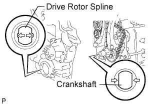
Align the oil pump's drive rotor spline and crankshaft as shown in the illustration. Install the spline and chain cover plate to the crankshaft.
-
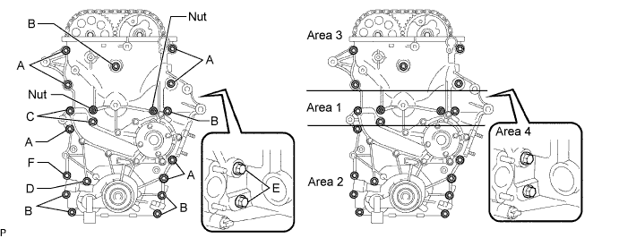
Loosely install the timing chain cover with the 19 bolts and 2 nuts, but do not tighten the bolts and nuts yet.
-
Excluding the bolts labeled A and C, tighten the bolts and nuts in this order: Area 1, Area 2 and Area 3.
- Torque:
- 21 N*m { 214 kgf*cm, 15 ft.*lbf }
Bolt Length Item Length Thread Diameter Bolt A 75 mm (2.95 in.) 10 mm (0.394 in.) Bolt B 75 mm (2.95 in.) 8 mm (0.315 in.) Bolt C 90 mm (3.54 in.) 8 mm (0.315 in.) Bolt D 95 mm (3.74 in.) 8 mm (0.315 in.) Bolt E 35 mm (1.38 in.) 8 mm (0.315 in.) Bolt F 75 mm (2.95 in.) 10 mm (0.394 in.) -
Excluding the bolts labeled A, E and F, tighten the bolts and nuts in this order: Area 1, Area 3, Area 2.
- Torque:
- for bolt C
- 26 N*m { 265 kgf*cm, 19 ft.*lbf }
- for bolt B, D and nut
- 21 N*m { 214 kgf*cm, 15 ft.*lbf }
-
Tighten the bolts labeled A in this order: Area 2 and Area 3.
- Torque:
- 60 N*m { 612 kgf*cm, 44 ft.*lbf }
-
Tighten the bolt labeled F.
- Torque:
- 46 N*m { 469 kgf*cm, 34 ft.*lbf }
-
Tighten the bolts labeled E in Area 4.
- Torque:
- 21 N*m { 214 kgf*cm, 15 ft.*lbf }
-
-
INSTALL NO. 1 OIL PAN
-
Install the stud bolt.
-
Using E5 and E7 "TORX" socket wrenches, install the stud bolts.
- Torque:
- 3.0 N*m { 31 kgf*cm, 27 in.*lbf }
-
-
Install a new tight plug.
-
Apply adhesive around a new tight plug.
Adhesive Toyota Genuine Adhesive 1324, Three Bond 1324 or equivalent -
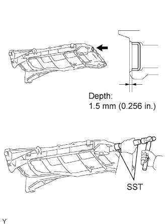
Using SST and a hammer, tap in the tight plug as shown in the illustration.
- SST
- 09950-60010 ( 09951-00300 )
- 09950-70010 ( 09951-07100 )
-
-
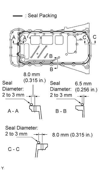
Apply seal packing in a continuous line to the places shown in the illustration.
Seal packing Toyota Genuine Seal Packing Black, Three Bond 1207B or equivalent Standard seal diameter 2 to 3 mm (0.08 to 0.12 in.) Note
-
Remove any oil from the contact surface.
-
Install the crankcase within 3 minutes after applying seal packing.
-
Do not start the engine for at least 4 hours after installing.
-
-
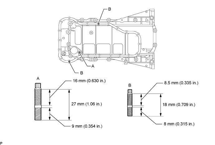
Temporarily install the oil pan with the 16 bolts and 2 nuts.
Tech Tips
Bolt length:
20 mm (0.79 in.) for bolt A
40 mm (1.57 in.) for bolt B
-
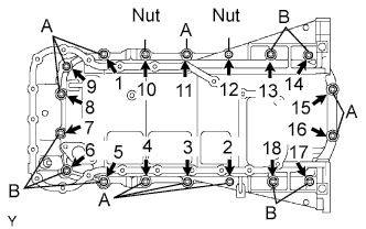
Uniformly tighten the 16 bolts and 2 nuts in the sequence shown in the illustration.
- Torque:
- 26 N*m { 265 kgf*cm, 19 ft.*lbf }
-
-
INSTALL OIL STRAINER
-
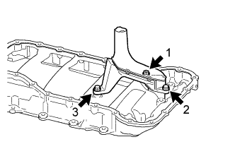
Install a new gasket and the oil strainer with the 2 bolts and nut in the sequence shown in the illustration.
- Torque:
- 10 N*m { 102 kgf*cm, 7 ft.*lbf }
-
-
INSTALL NO. 2 OIL PAN
-
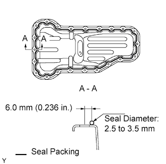
Apply seal packing in a continuous line as shown in the illustration.
Seal packing Toyota Genuine Seal Packing Black, Three Bond 1207B or equivalent Standard seal diameter 2.5 to 3.5 mm (0.098 to 0.138 in.) Note
-
Remove any oil from the contact surface.
-
Install the oil pan within 3 minutes after applying seal packing.
-
Do not start the engine for at least 4 hours after the installation.
-
-
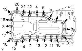
Temporarily install the oil pan with the 20 bolts and 2 nuts.
-
Uniformly tighten the 20 bolts and 2 nuts in the order shown in the illustration.
- Torque:
- 9.0 N*m { 92 kgf*cm, 80 in.*lbf }
-
Install a new gasket and the drain plug.
- Torque:
- 37.5 N*m { 382 kgf*cm, 28 ft.*lbf }
-
-
CHECK CRANKSHAFT PULLEY
-
Check that the crankshaft pulley matches the pulley labeled A in the illustration.
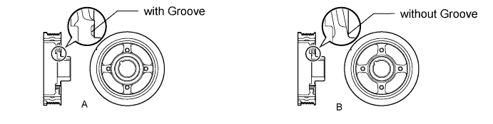
Note
If the crankshaft pulley matches the pulley labeled B, replace the crankshaft pulley.
-
-
INSTALL CRANKSHAFT PULLEY
-
Align the pulley set key with the key groove of the pulley, and slide on the pulley.
-
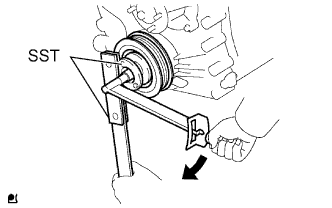
Using SST, install a new pulley bolt.
- SST
- 09213-54015 ( 91651-60855 )
- 09330-00021
- Torque:
- 260 N*m { 2651 kgf*cm, 192 ft.*lbf }
Note
Do not reuse the pulley bolt.
-
-
INSTALL CYLINDER HEAD COVER
-
Install the 2 gaskets to the head cover.
-
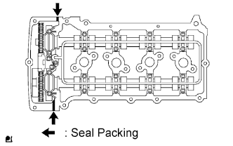
Apply seal packing to the places shown in the illustration.
Seal packing Toyota Genuine Seal Packing Black, Three Bond 1207B or equivalent Note
-
Remove any oil from the contact surface.
-
Install the crankcase within 3 minutes after applying seal packing.
-
Do not start the engine for at least 2 hours after installing.
-
-
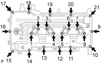
Temporarily install the cover with the 19 bolts and 2 nuts.
-
Uniformly tighten the 19 bolts and 2 nuts in the sequence shown in the illustration.
- Torque:
- 9.0 N*m { 92 kgf*cm, 80 in.*lbf }
-
In numerical order, confirm that the bolts labeled 1 to 8 are tighten to the torque specification. Tighten the bolts as necessary.
-
-
INSTALL VENTILATION VALVE
-
Install the ventilation valve to the head cover.
- Torque:
- 5.0 N*m { 51 kgf*cm, 44 in.*lbf }
-
-
INSTALL OIL FILLER CAP