SFI SYSTEM (w/o Secondary Air Injection System) Fuel Injector Circuit
DESCRIPTION
The fuel injectors are located on the intake manifold. They inject fuel into the cylinders based on the signals from the ECM.
WIRING DIAGRAM
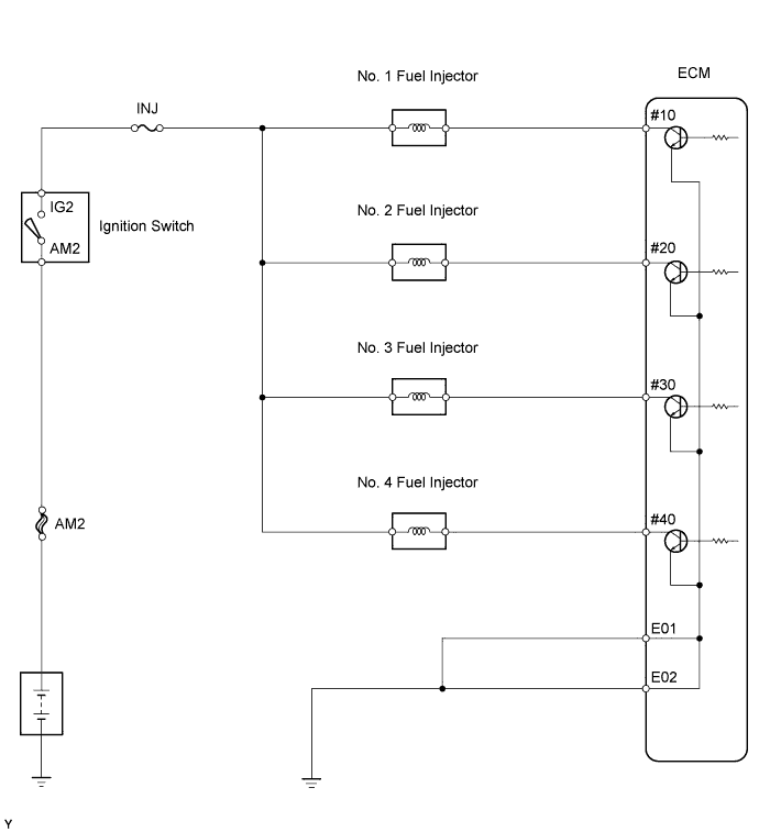
INSPECTION PROCEDURE
PROCEDURE
-
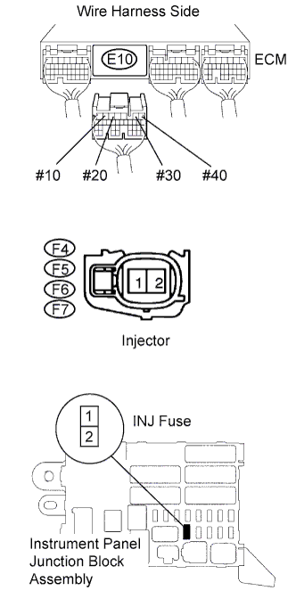
CHECK ECM (#10, #20, #30, #40 VOLTAGE)
-
Turn the ignition switch ON.
-
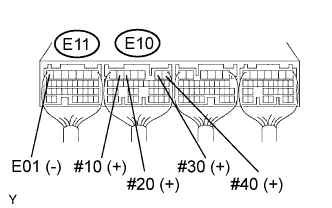
Measure the voltage of the ECM connectors.
Standard voltage Tester Connection Specified Condition E10-6 (#10) - E11-7 (E01) 9 to 14 V E10-5 (#20) - E11-7 (E01) 9 to 14 V E10-2 (#30) - E11-7 (E01) 9 to 14 V E10-1 (#40) - E11-7 (E01) 9 to 14 V 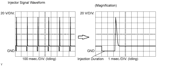
Tech Tips
Reference: Inspect using the oscilloscope.
Check the waveform of the ECM connector.
OK Tester Connection Specified Condition E10-6 (#10) - E11-7 (E01) Correct waveform is as shown E10-5 (#20) - E11-7 (E01) Correct waveform is as shown E10-2 (#30) - E11-7 (E01) Correct waveform is as shown E10-1 (#40) - E11-7 (E01) Correct waveform is as shown Tool Setting Condition 20 V/DIV., 100 or 1 msec./DIV. Idling
OK 
CHECK WIRE HARNESS (ECM - BODY GROUND) Click here
NG 
-
-
INSPECT FUEL INJECTOR ASSEMBLY (RESISTANCE)
-
Inspect fuel injector Click here.
NG 
REPLACE FUEL INJECTOR ASSEMBLY
OK
-
-
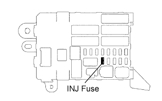
INSPECT FUSE (INJ)
-
Remove the INJ fuse from the instrument panel junction block.
-
Measure the resistance of the fuse.
Standard resistance Below 1 Ω
NG
CHECK FOR SHORT IN ALL HARNESSES AND COMPONENTS CONNECTED TO FUSE
OK
-
-
CHECK WIRE HARNESS OF MISFIRING CYLINDER (INJECTOR - ECM, INJECTOR - INJ FUSE)
-
Check the wire harness between the injector and ECM.
-
Disconnect the F4, F5, F6 and/or F7 injector connectors.
-
Disconnect the E10 ECM connector.
-
Measure the resistance of the wire harness side connectors.
Standard resistance Tester Connection Specified Condition F4-2 - E10-6 (#10) Below 1 Ω F5-2 - E10-5 (#20) Below 1 Ω F6-2 - E10-2 (#30) Below 1 Ω F7-2 - E10-1 (#40) Below 1 Ω F4-2 or E10-6 (#10) - Body ground 10 kΩ or higher F5-2 or E10-5 (#20) - Body ground 10 kΩ or higher F6-2 or E10-2 (#30) - Body ground 10 kΩ or higher F7-2 or E10-1 (#40) - Body ground 10 kΩ or higher
-
-
Check the wire harness between the injector and INJ fuse.
-
Disconnect the F4, F5, F6 and F7 injector connectors.
-
Remove the INJ fuse from the instrument panel junction block.
-
Measure the resistance of the wire harness side connectors.
Standard resistance Tester Connection Specified Condition F4-1 - J/B INJ fuse terminal 2 Below 1 Ω F5-1 - J/B INJ fuse terminal 2 Below 1 Ω F6-1 - J/B INJ fuse terminal 2 Below 1 Ω F7-1 - J/B INJ fuse terminal 2 Below 1 Ω F4-1 or J/B INJ fuse terminal 2 - Body ground 10 kΩ or higher F5-1 or J/B INJ fuse terminal 2 - Body ground 10 kΩ or higher F6-1 or J/B INJ fuse terminal 2 - Body ground 10 kΩ or higher F7-1 or J/B INJ fuse terminal 2 - Body ground 10 kΩ or higher
-
NG
REPAIR OR REPLACE HARNESS AND CONNECTOR
OK
-
-
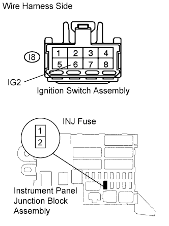
CHECK WIRE HARNESS (IGNITION SWITCH - INJ FUSE)
-
Disconnect the I8 ignition switch connector.
-
Remove the INJ fuse from the instrument panel junction block.
-
Measure the resistance of the wire harness side connectors.
Standard resistance Tester Connection Specified Condition I8-6 (IG2) - J/B INJ fuse terminal 1 Below 1 Ω I8-6 (IG2) or J/B INJ fuse terminal 1 - Body ground 10 kΩ or higher
NG
REPAIR OR REPLACE HARNESS AND CONNECTOR
OK 
CHECK FOR ECM POWER SOURCE CIRCUIT
-
-
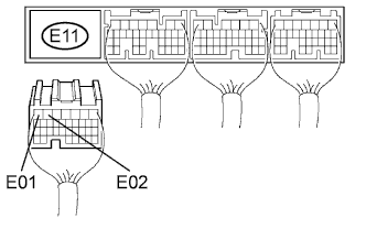
CHECK WIRE HARNESS (ECM - BODY GROUND)
-
Disconnect the E11 ECM connector.
-
Measure the resistance of the wire harness side connector.
Standard resistance Tester Connection Specified Condition E11-7 (E01) - Body ground Below 1 Ω E11-6 (E02) - Body ground Below 1 Ω
NG
REPAIR OR REPLACE HARNESS AND CONNECTOR
OK
-
-
INSPECT FUEL INJECTOR ASSEMBLY (CHECK FUEL INJECTION VOLUME)
-
Inspect fuel injector Click here.
NG
REPLACE FUEL INJECTOR ASSEMBLY
OK
PROCEED TO NEXT CIRCUIT INSPECTION SHOWN IN PROBLEM SYMPTOMS TABLE
-