SFI SYSTEM (w/o Secondary Air Injection System) Fuel Pump Control Circuit
DESCRIPTION
When the engine is cranked, current flows from terminal ST2 of the ignition switch to the starter relay (Marking: ST) coil, and current also flows to terminal STA of the ECM (STA signal).
When the STA signal and NE signal are transmitted to the ECM, the power transistor (Tr) is turned ON, current flows to the circuit opening relay (Marking: C/OPN) coil, the relay switches on, power is supplied to the fuel pump and the fuel pump operates.
While the NE signal is generated (when engine running), the ECM keeps Tr ON (circuit opening relay ON) and the fuel pump also keeps operating.
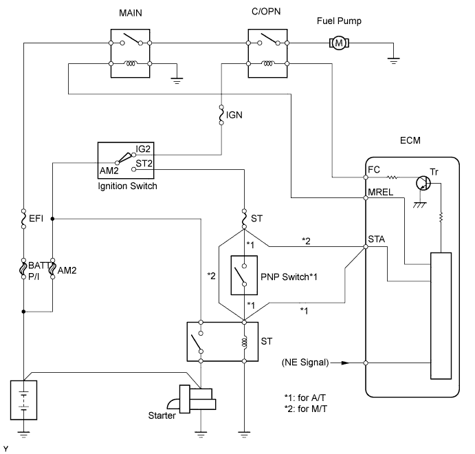
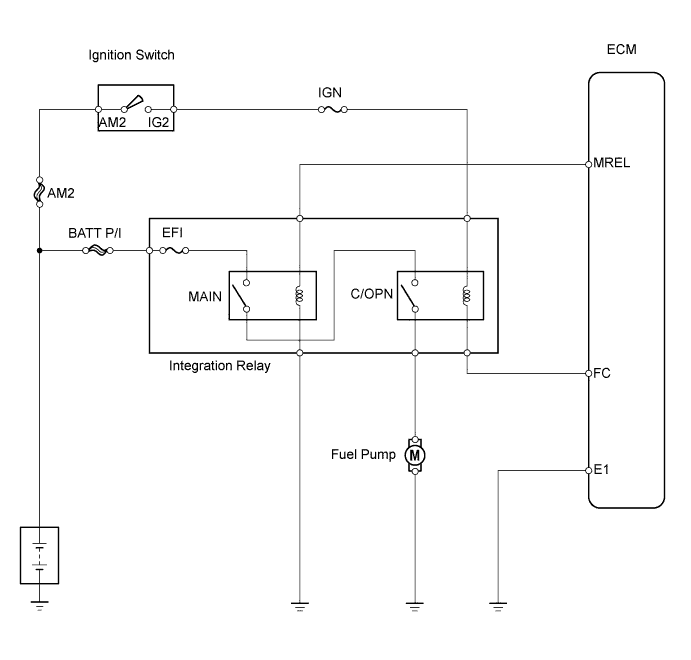
WIRING DIAGRAM
INSPECTION PROCEDURE
When using intelligent tester:
PROCEDURE
-
PERFORM ACTIVE TEST (OPERATE C/OPN RELAY)
-
Connect the intelligent tester to the DLC3.
-
Turn the ignition switch ON and turn the intelligent tester ON.
-
Enter the following menus: Powertrain / Engine and ECT / Active Test / Fuel Pump.
-
Check the operation of the relay while operating it using the intelligent tester.
OK Operating noise can be heard from the fuel pump.
OK 
PROCEED TO NEXT CIRCUIT INSPECTION SHOWN IN PROBLEM SYMPTOMS TABLE
NG 
-
-
CHECK ECM POWER SOURCE CIRCUIT
-
Check ECM Power Source Circuit Click here.
NG
REPAIR OR REPLACE POWER SOURCE CIRCUIT
OK
-
-
CHECK ECM (FC VOLTAGE)
-
Turn the ignition switch ON.
-
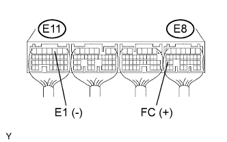
Measure the voltage of the ECM connectors.
Standard voltage Tester Connection Specified Condition E8-25 (FC) - E11-3 (E1) 9 to 14 V
NG 
CHECK WIRE HARNESS (INTEGRATION RELAY (C/OPN RELAY) - ECM AND BODY GROUND) Click here
OK
-
-
CHECK INTEGRATION NO.1 RELAY (C/OPN RELAY)
-
Remove the integration relay from the engine room junction block.
-
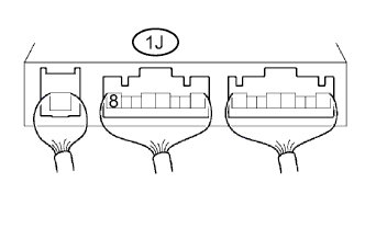
Measure the voltage of the C/OPN relay.
Standard voltage Terminal Connection Condition Specified Condition 1J-8 - Body ground Ignition Switch ON 10 to 14 V
NG
REPLACE INTEGRATION NO.1 RELAY
OK
-
-
INSPECT FUEL PUMP
-
Inspect the fuel pump Click here.
NG
REPLACE FUEL PUMP
OK
-
-
CHECK WIRE HARNESS (FUEL PUMP - INTEGRATION RELAY (C/OPN RELAY) AND BODY GROUND)
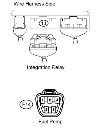
-
Remove the integration relay from the engine room junction block.
-
Disconnect the 1J integration relay connector.
-
Disconnect the F14 fuel pump connector.
-
Measure the resistance of the wire harness side connectors.
Standard resistance Tester Connection Specified Condition 1J-8 - F14-4 Below 1 Ω F14-5 - Body ground Below 1 Ω 1J-8 or F14-4 - Body ground 10 kΩ or higher
NG
REPAIR OR REPLACE HARNESS AND CONNECTOR
OK 
REPLACE ECM
-
-
CHECK WIRE HARNESS (INTEGRATION RELAY (C/OPN RELAY) - ECM AND BODY GROUND)
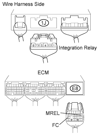
-
Remove the integration relay from the engine room junction block.
-
Disconnect the 1J integration relay connector.
-
Measure the voltage of the wire harness side connectors.
Standard voltage Tester Connection Specified Condition 1J-6 - Body ground 9 to 14 V -
Disconnect the E8 ECM connector.
-
Measure the resistance of the wire harness side connectors.
Standard resistance Tester Connection Specified Condition 1J-7 - E8-25 (FC) Below 1 Ω 1J-7 or E8-25 (FC) - Body ground 10 kΩ or higher
NG
REPAIR OR REPLACE HARNESS AND CONNECTOR
OK
REPLACE ECM
-
When not using intelligent tester:
PROCEDURE
-
INSPECT OPERATION OF FUEL PUMP
-
Start the engine.
-
Check whether operating sounds can be heard while operating the fuel pump.
OK Operating sounds can be heard from fuel pump.
OK
PROCEED TO NEXT CIRCUIT INSPECTION SHOWN IN PROBLEM SYMPTOMS TABLE
NG
-
-
CHECK ECM POWER SOURCE CIRCUIT
-
Check ECM Power Source Circuit Click here.
NG
REPAIR OR REPLACE POWER SOURCE CIRCUIT
OK
-
-
CHECK ECM (FC VOLTAGE)
-
Turn the ignition switch ON.
-
Measure the voltage of the ECM connectors.
Standard voltage Tester Connection Specified Condition E8-25 (FC) - E11-3 (E1) 9 to 14 V
NG
CHECK WIRE HARNESS (INTEGRATION RELAY (C/OPN RELAY) - ECM AND BODY GROUND) Click here
OK
-
-
CHECK INTEGRATION NO.1 RELAY (C/OPN RELAY)
-
Remove the integration relay from the engine room junction block.
-
Measure the voltage of the C/OPN relay.
Standard voltage Tester Connection Condition Specified Condition 1J-8 - Body ground Ignition switch ON 10 to 14 V
NG
REPLACE INTEGRATION NO.1 RELAY
OK
-
-
INSPECT FUEL PUMP
-
Inspect the fuel pump Click here.
NG
REPLACE FUEL PUMP
OK
-
-
CHECK WIRE HARNESS (FUEL PUMP - INTEGRATION RELAY (C/OPN RELAY) AND BODY GROUND)
-
Disconnect the 1J integration relay connector from the engine room junction block.
-
Disconnect the F14 fuel pump connector.
-
Measure the resistance of the wire harness side connectors.
Standard resistance Tester Connection Specified Condition 1J-8 - F14-4 Below 1 Ω F14-5 - Body ground Below 1 Ω 1J-8 or F14-4 - Body ground 10 kΩ or higher
NG
REPAIR OR REPLACE HARNESS AND CONNECTOR
OK
REPLACE ECM
-
-
CHECK WIRE HARNESS (INTEGRATION RELAY (C/OPN RELAY) - ECM AND BODY GROUND)
-
Remove the integration relay from the engine room junction block.
-
Disconnect the 1J integration relay connector.
-
Measure the voltage of the wire harness side connectors.
Standard voltage Tester Connection Specified Condition 1J-6 - Body ground 9 to 14 V -
Disconnect the E8 ECM connector.
-
Measure the resistance of the wire harness side connectors.
Standard resistance Tester Connection Specified Condition 1J-7 - E8-25 (FC) Below 1 Ω 1J-7 or E8-25 (FC) - Body ground 10 kΩ or higher
NG
REPAIR OR REPLACE HARNESS AND CONNECTOR
OK
REPLACE ECM
-