SFI SYSTEM (w/o Secondary Air Injection System), Diagnostic DTC:P2121/19

| DTC Code | DTC Name |
|---|---|
| P2121/19 | Throttle / Pedal Position Sensor / Switch "D" Circuit Range / Performance |
DESCRIPTION
Tech Tips
This DTC is related to the accelerator pedal position sensor.
Refer to DTC P2120/19 Click here.
| DTC No. | DTC Detection Condition | Trouble Area |
|---|---|---|
| P2121/19 | Either of following conditions 1 or 2 met for 0.5 seconds
|
|
MONITOR DESCRIPTION
When the difference between the output voltages of VPA and VPA2 deviates from the standard, the ECM determines that the accelerator pedal position sensor is malfunctioning. The ECM turns on the MIL and stores the DTC.
FAIL-SAFE
The accelerator pedal position sensor has a main circuit and associated circuit. When one circuit is malfunctioning, the accelerator pedal position is calculated by the output of the other circuit. When both of the circuits are malfunctioning, it is interpreted that the accelerator pedal is released. As a result, throttle valve is closed and engine idles.
WIRING DIAGRAM
Refer to DTC P2120/19 Click here.
INSPECTION PROCEDURE
Tech Tips
Read freeze frame data using the intelligent tester. Freeze frame data records the engine conditions when malfunctions are detected. When troubleshooting, freeze frame data can help determine if the vehicle was moving or stationary, if the engine was warmed up or not, if the air-fuel ratio was lean or rich, and other data from the time the malfunction occurred.
When using intelligent tester:
PROCEDURE
-
READ DATA LIST (ACCELERATOR POSITION NO. 1, ACCELERATOR POSITION NO. 2)
-
Connect the intelligent tester to the DLC3.
-
Turn the ignition switch ON and turn the intelligent tester ON.
-
Enter the following menus: Powertrain / Engine and ECT / Data List / Accelerator Position No. 1 and Accelerator Position No. 2.
-
Read the values.
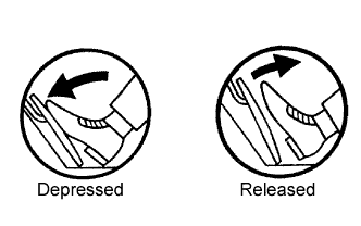
Standard voltage Accelerator Pedal Accelerator Position No. 1 Accelerator Position No. 2 Released 0.5 to 1.1 V 1.2 to 2.0 V Depressed 2.6 to 4.5 V 3.4 to 5.0 V
OK 
REPLACE ECM
NG 
-
-
CHECK WIRE HARNESS (ACCELERATOR PEDAL POSITION SENSOR - ECM)
-
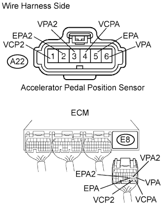
Disconnect the A22 accelerator pedal position sensor connector.
-
Disconnect the E8 ECM connector.
-
Measure the resistance of the wire harness side connectors.
Standard resistance Tester Connection Specified Condition A22-6 (VPA) - E8-18 (VPA) Below 1 Ω A22-5 (EPA) - E8-20 (EPA) Below 1 Ω A22-4 (VCPA) - E8-26 (VCPA) Below 1 Ω A22-3 (VPA2) - E8-19 (VPA2) Below 1 Ω A22-2 (EPA2) - E8-21 (EPA2) Below 1 Ω A22-1 (VCP2) - E8-27 (VCP2) Below 1 Ω A22-6 (VPA) or E8-18 (VPA) - Body ground 10 kΩ or higher A22-5 (EPA) or E8-20 (EPA) - Body ground 10 kΩ or higher A22-4 (VCPA) or E8-26 (VCPA) - Body ground 10 kΩ or higher A22-3 (VPA2) or E8-19 (VPA2) - Body ground 10 kΩ or higher A22-2 (EPA2) or E8-21 (EPA2) - Body ground 10 kΩ or higher A22-1 (VCP2) or E8-27 (VCP2) - Body ground 10 kΩ or higher
NG
REPAIR OR REPLACE HARNESS AND CONNECTOR
OK 
REPLACE ACCELERATOR PEDAL ROD
-
When not using intelligent tester:
PROCEDURE
-
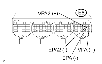
CHECK ECM (VPA, VPA2 VOLTAGE)
-
Turn the ignition switch ON.
-
Measure the voltage of the ECM connector.
Standard voltage Tester Connection Accelerator Pedal Condition Specified Condition E8-18 (VPA) - E8-20 (EPA) Released 0.5 to 1.1 V E8-18 (VPA) - E8-20 (EPA) Depressed 2.5 to 4.6 V E8-19 (VPA2) - E8-21 (EPA2) Released 1.5 to 2.9 V E8-19 (VPA2) - E8-21 (EPA2) Depressed 3.5 to 5.0 V
OK
REPLACE ECM
NG
-
-
CHECK WIRE HARNESS (ACCELERATOR PEDAL POSITION SENSOR - ECM)
-
Disconnect the A22 accelerator pedal position sensor connector.
-
Disconnect the E8 ECM connector.
-
Measure the resistance of the wire harness side connectors.
Standard resistance Tester Connection Specified Condition A22-6 (VPA) - E8-18 (VPA) Below 1 Ω A22-5 (EPA) - E8-20 (EPA) Below 1 Ω A22-4 (VCPA) - E8-26 (VCPA) Below 1 Ω A22-3 (VPA2) - E8-19 (VPA2) Below 1 Ω A22-2 (EPA2) - E8-21 (EPA2) Below 1 Ω A22-1 (VCP2) - E8-27 (VCP2) Below 1 Ω A22-6 (VPA) or E8-18 (VPA) - Body ground 10 kΩ or higher A22-5 (EPA) or E8-20 (EPA) - Body ground 10 kΩ or higher A22-4 (VCPA) or E8-26 (VCPA) - Body ground 10 kΩ or higher A22-3 (VPA2) or E8-19 (VPA2) - Body ground 10 kΩ or higher A22-2 (EPA2) or E8-21 (EPA2) - Body ground 10 kΩ or higher A22-1 (VCP2) or E8-27 (VCP2) - Body ground 10 kΩ or higher
NG
REPAIR OR REPLACE HARNESS AND CONNECTOR
OK
REPLACE ACCELERATOR PEDAL ROD
-