SFI SYSTEM (w/o Secondary Air Injection System), Diagnostic DTC:P0504/51

| DTC Code | DTC Name |
|---|---|
| P0504/51 | Brake Switch "A" / "B" Correlation |
DESCRIPTION
In this system, the signals of the stop light switch's duplex system (STP and ST1-) are used to judge whether the brake system is abnormal or not. When the signals of depressing and releasing the brake pedal are detected simultaneously, the ECM interprets this as a malfunction of the stop light switch.
| Signal | Brake Pedal Released | In Transition | Brake Pedal Depressed |
|---|---|---|---|
| STP | OFF | ON | ON |
| ST1- | ON | ON | OFF |
Tech Tips
The normal condition of the signals is shown in the table above.
| DTC No. | DTC Detection Condition | Trouble Area |
|---|---|---|
| P0504/51 | Conditions (a), (b) and (c) continue for 0.5 seconds or more:
|
|
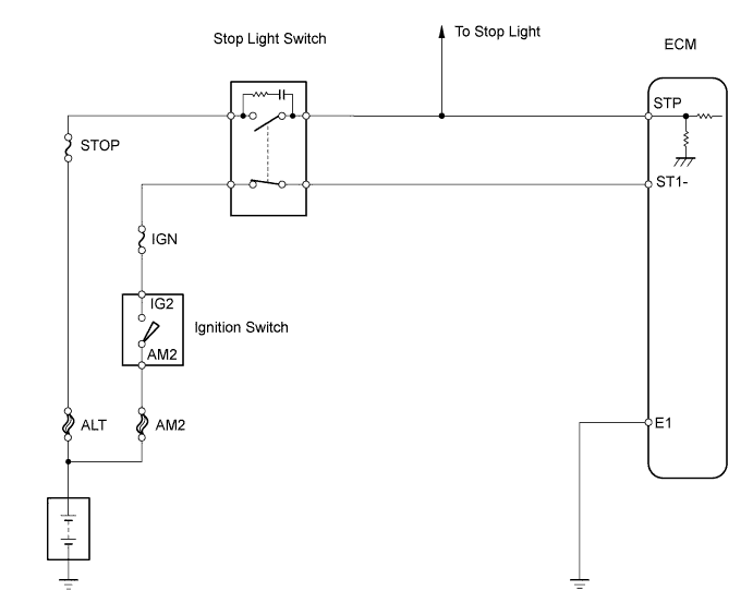
WIRING DIAGRAM
INSPECTION PROCEDURE
Tech Tips
Read freeze frame data using the intelligent tester. Freeze frame data records the engine conditions when malfunctions are detected. When troubleshooting, freeze frame data can help determine if the vehicle was moving or stationary, if the engine was warmed up or not, if the air-fuel ratio was lean or rich, and other data from the time the malfunction occurred.
When using intelligent tester:
PROCEDURE
-
CHECK STOP LIGHT (OPERATION)
-
Check that the stop lights turn ON and OFF when the brake pedal is depressed and released, respectively.
OK Stop lights turn ON and OFF when brake pedal is depressed and released, respectively.
NG 
REPAIR OR REPLACE STOP LIGHT SWITCH CIRCUIT
OK 
-
-
READ DATA LIST (STP SIGNAL, ST1- VOLTAGE)
-
Connect the intelligent tester to the DLC3.
-
Turn the ignition switch ON and turn the intelligent tester ON.
-
Enter the following menus: Powertrain / Engine and ECT / Data List / Stop Light Switch.
-
Check the STP signal when depressing and releasing the brake pedal.
OK Brake Pedal Condition Specified Condition Depressed STP Signal ON Released STP Signal OFF -
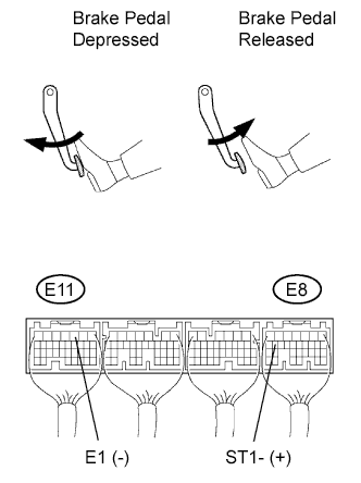
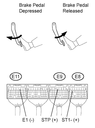
Measure the voltage of the ECM connectors.
Standard voltage Tester Connection Brake Pedal Condition Specified Condition E8-16 (ST1-) - E11-3 (E1) Depressed Below 1.5 V E8-16 (ST1-) - E11-3 (E1) Released 7.5 to 14 V
OK
CHECK FOR INTERMITTENT PROBLEMS
NG
-
-
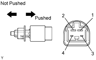
INSPECT STOP LIGHT SWITCH ASSEMBLY
-
Measure the resistance of the switch.
Standard resistance Tester Connection Switch Condition Specified Condition 1 - 2 Pin not pushed Below 1 Ω 3 - 4 Pin not pushed 10 kΩ or higher 1 - 2 Pin pushed 10 kΩ or higher 3 - 4 Pin pushed Below 1 Ω
NG
REPLACE STOP LIGHT SWITCH ASSEMBLY
OK
-
-
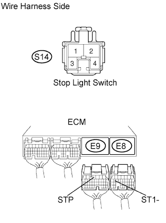
CHECK WIRE HARNESS (STOP LIGHT SWITCH - ECM)
-
Disconnect the E8 and E9 ECM connectors.
-
Disconnect the S14 stop light switch connector.
-
Measure the resistance of the wire harness side connectors.
Standard resistance Tester Connection Specified Condition S14-1 - E9-4 (STP) Below 1 Ω S14-4 - E8-16 (ST1-) Below 1 Ω S14-1 or E9-4 (STP) - Body ground 10 kΩ or higher S14-4 or E8-16 (ST1-) - Body ground 10 kΩ or higher
NG
REPAIR OR REPLACE HARNESS AND CONNECTOR
OK 
REPLACE ECM
-
When not using intelligent tester:
PROCEDURE
-
CHECK STOP LIGHT (OPERATION)
-
Check that the stop lights turn ON and OFF when the brake pedal is depressed and released, respectively.
OK Stop lights turn ON and OFF when brake pedal is depressed and released, respectively.
NG
REPAIR OR REPLACE STOP LIGHT SWITCH CIRCUIT
OK
-
-
CHECK ECM (STP, ST1- VOLTAGE)
-
Turn the ignition switch ON.
-
Measure the voltage of the ECM connectors.
Standard voltage Tester Connection Brake Pedal Condition Specified Condition E9-4 (STP) - E11-3 (E1) Depressed 7.5 to 14 V E9-4 (STP) - E11-3 (E1) Released Below 1.5 V E8-16 (ST1-) - E11-3 (E1) Depressed Below 1.5 V E8-16 (ST1-) - E11-3 (E1) Released 7.5 to 14 V
OK
CHECK FOR INTERMITTENT PROBLEMS
NG
-
-
INSPECT STOP LIGHT SWITCH ASSEMBLY
-
Measure the resistance of the switch.
Standard resistance Tester Connection Switch Condition Specified Condition 1 - 2 Pin not pushed Below 1 Ω 3 - 4 Pin not pushed 10 kΩ or higher 1 - 2 Pin pushed 10 kΩ or higher 3 - 4 Pin pushed Below 1 Ω
NG
REPLACE STOP LIGHT SWITCH ASSEMBLY
OK
-
-
CHECK WIRE HARNESS (STOP LIGHT SWITCH - ECM)
-
Disconnect the E8 and E9 ECM connectors.
-
Disconnect the S14 stop light switch connector.
-
Measure the resistance of the wire harness side connectors.
Standard resistance Tester Connection Specified Condition S14-1 - E9-4 (STP) Below 1 Ω S14-4 - E8-16 (ST1-) Below 1 Ω S14-1 or E9-4 (STP) - Body ground 10 kΩ or higher S14-4 or E8-16 (ST1-) - Body ground 10 kΩ or higher
NG
REPAIR OR REPLACE HARNESS AND CONNECTOR
OK
REPLACE ECM
-