SFI SYSTEM (w/o Secondary Air Injection System), Diagnostic DTC:P0335/13, P0339/13

| DTC Code | DTC Name |
|---|---|
| P0335/13 | Crankshaft Position Sensor "A" Circuit |
| P0339/13 | Crankshaft Position Sensor "A" Circuit Intermittent |
DESCRIPTION
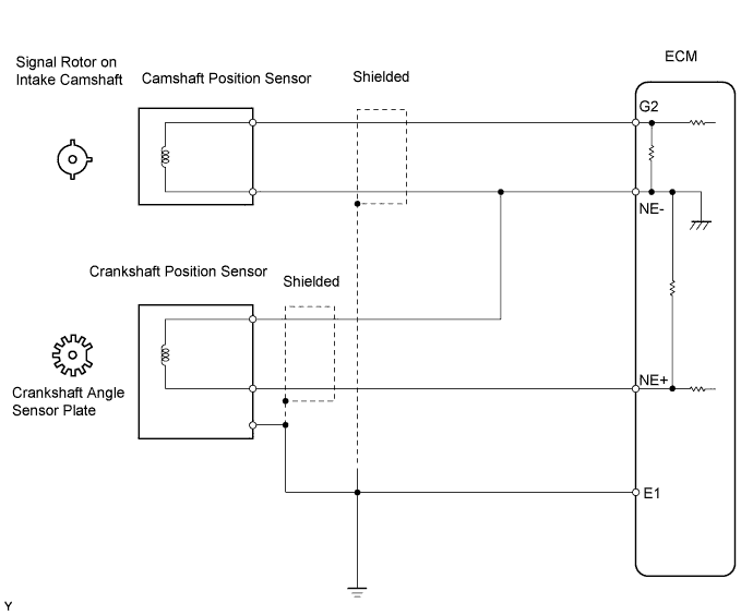
The crankshaft position sensor system consists of a crankshaft position sensor plate and pickup coil. The sensor plate has 34 teeth and is installed on the crankshaft. The pickup coil is made of an iron core and magnet. The sensor plate rotates and as each tooth passes through the pickup coil, a pulse signal is created. The pickup coil generates 34 signals per engine revolution. Based on these signals, the ECM calculates the crankshaft position and engine rpm. Using these calculations, the fuel injection time and ignition timing are controlled.
| DTC No. | DTC Detection Condition | Trouble Area |
|---|---|---|
| P0335/13 | No crankshaft position sensor signal to ECM at engine speed of 600 rpm or more (1 trip detection logic) |
|
| P0339/13 | In conditions (a), (b) and (c), when no crankshaft position sensor signal to ECM for 0.05 seconds or more.
|
|
MONITOR DESCRIPTION
If there is no signal from the crankshaft position sensor even though the engine is running, the ECM interprets this as a malfunction of the sensor.
This monitor runs for 10 seconds (the first 10 seconds of engine idle) after the engine is started.
WIRING DIAGRAM
INSPECTION PROCEDURE
Tech Tips
-
If no problem is found in the diagnostic troubleshooting procedure of DTC P0335, troubleshoot the engine mechanical systems.
-
Read the value on the intelligent tester.
(a) Connect the intelligent tester to the DLC3.
(b) Start the engine and turn the intelligent tester ON.
(c) Enter the following menu items: Powertrain / Engine and ECT / Data List / Engine Speed.
-
The engine speed can be confirmed in the Data List using the intelligent tester. If there are no NE signals from the crankshaft position sensor despite the engine running, the engine speed will be indicated as 0. If the voltage output of the crankshaft position sensor is insufficient, the engine speed will be indicated as lower than the actual engine rpm.
-
Read freeze frame data using the intelligent tester. Freeze frame data records the engine conditions when malfunctions are detected. When troubleshooting, freeze frame data can help determine if the vehicle was moving or stationary, if the engine was warmed up or not, if the air-fuel ratio was lean or rich, and other data from the time the malfunction occurred.
PROCEDURE
-
INSPECT CRANKSHAFT POSITION SENSOR (RESISTANCE)
-
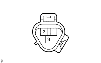
Disconnect the C5 sensor connector.
-
Measure the resistance of the sensor.
Standard resistance Tester Connection Sensor Condition Specified Condition 1 - 2 Cold 1,630 to 2,740 Ω 1 - 2 Hot 2,065 to 3,225 Ω Note
In the chart above, the terms "cold" and "hot" refer to the temperature of the sensor. "Cold" means approximately -10 to 50°C (14 to 122°F). "Hot" means approximately 50 to 100°C (122 to 212°F).
NG 
REPLACE CRANKSHAFT POSITION SENSOR
OK 
-
-
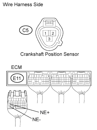
CHECK WIRE HARNESS (CRANKSHAFT POSITION SENSOR - ECM)
-
Disconnect the C5 sensor connector.
-
Disconnect the E11 ECM connector.
-
Measure the resistance of the wire harness side connectors.
Standard resistance Tester Connection Specified Condition C5-1 - E11-27 (NE+) Below 1 Ω C5-2 - E11-34 (NE-) Below 1 Ω C5-1 or E11-27 (NE+) - Body ground 10 kΩ or higher C5-2 or E11-34 (NE-) - Body ground 10 kΩ or higher
NG
REPAIR OR REPLACE HARNESS AND CONNECTOR
OK
-
-
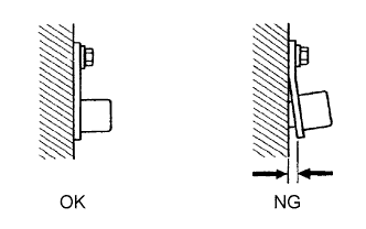
CHECK CRANKSHAFT POSITION SENSOR (INSTALLATION)
-
Check that the crankshaft position sensor is installed correctly.
OK Sensor is installed correctly.
NG
SECURELY REINSTALL CRANKSHAFT POSITION SENSOR
OK
-
-
CHECK CRANKSHAFT POSITION SENSOR PLATE (TEETH)
-
Check that the teeth of the sensor plate do not have any cracks or deformation.
OK Teeth of sensor plate do not have cracks or deformation.
NG
REPLACE CRANKSHAFT POSITION SENSOR PLATE
OK 
REPLACE ECM
-