SFI SYSTEM (w/o Secondary Air Injection System), Diagnostic DTC:P0135/21

| DTC Code | DTC Name |
|---|---|
| P0135/21 | Oxygen Sensor Heater Circuit (Bank 1 Sensor 1) |
DESCRIPTION
Refer to DTC P0130/21 Click here.
| DTC No. | DTC Detection Condition | Trouble Area |
|---|---|---|
| P0135/21 | Open or short in heater circuit of oxygen sensor for 0.5 seconds or more |
|
Tech Tips
Sensor 1 refers to the sensor closer to the engine assembly.
WIRING DIAGRAM
Refer to DTC P0130/21 Click here.
INSPECTION PROCEDURE
Tech Tips
Read freeze frame data using the intelligent tester. Freeze frame data records the engine conditions when malfunctions are detected. When troubleshooting, freeze frame data can help determine if the vehicle was moving or stationary, if the engine was warmed up or not, if the air-fuel ratio was lean or rich, and other data from the time the malfunction occurred.
PROCEDURE
-
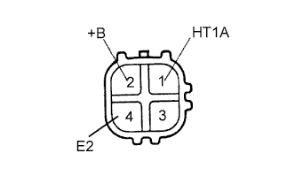
INSPECT HEATED OXYGEN SENSOR
-
Disconnect the H9 sensor connector.
-
Measure the resistance of the sensor.
Standard resistance Tester Connection Condition Specified Condition 1 (HT1A) - 2 (+B) 20°C (68°F) 5 to 10 Ω 1 (HT1A) - 4 (E2) - 10 kΩ or higher
NG 
REPLACE HEATED OXYGEN SENSOR
OK 
-
-
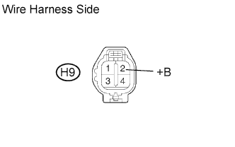
CHECK WIRE HARNESS (+B VOLTAGE)
-
Disconnect the H9 heated oxygen sensor connector.
-
Turn the ignition switch ON.
-
Measure the voltage of the wire harness side connector.
Standard voltage Tester Connection Specified Condition H9-2 (+B) - Body ground 9 to 14 V
OK 
CHECK WIRE HARNESS (HEATED OXYGEN SENSOR - ECM, INTEGRATION RELAY (MAIN RELAY)) Click here
NG
-
-
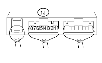
INSPECT INTEGRATION NO.1 RELAY (MAIN RELAY)
-
Remove the integration relay from the engine room junction block.
-
Measure the voltage of the MAIN relay.
Standard voltage Tester Connection Condition Specified Condition 1J-5 - Body ground Ignition switch ON 10 to 14 V
NG
REPLACE INTEGRATION NO.1 RELAY
OK
-
-
CHECK WIRE HARNESS (HEATED OXYGEN SENSOR - ECM, INTEGRATION RELAY (MAIN RELAY))

-
Disconnect the H9 sensor connector.
-
Disconnect the E11 ECM connector.
-
Remove the integration relay from the engine room junction block.
-
Disconnect the 1J integration relay connector.
-
Measure the resistance of the wire harness side connectors.
Standard resistance Tester Connection Specified Condition H9-1 (HT1A) - E11-1 (HT1A) Below 1 Ω H9-2 (+B) - 1J-5 Below 1 Ω H9-1 (HT1A) or E11-1 (HT1A) - Body ground 10 kΩ or higher H9-2 (+B) or 1J-5 - Body ground 10 kΩ or higher
NG
REPAIR OR REPLACE HARNESS AND CONNECTOR
OK
-
-
CHECK IF DTC OUTPUT RECURS
-
Connect the intelligent tester to the DLC3.
-
Turn the ignition switch ON and turn the tester ON.
-
Enter the following menus: Powertrain / Engine and ECT / DTC.
-
Read the DTCs.
Result Display (DTC output) Proceed to No output A Heated oxygen sensor circuit DTCs B
B
REPLACE ECM
A 
CHECK FOR INTERMITTENT PROBLEMS
-