SFI SYSTEM (w/o Secondary Air Injection System), Diagnostic DTC:P0130/21

| DTC Code | DTC Name |
|---|---|
| P0130/21 | Oxygen Sensor Circuit (Bank 1 Sensor 1) |
DESCRIPTION
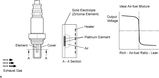
The front Heated Oxygen (HO2) sensor monitors the oxygen concentration in the exhaust gas. For optimum three-way catalytic converter operation, the air-fuel mixture must be maintained as close as possible to the stoichiometric ratio. The HO2 sensor output voltage changes dramatically in the vicinity of the stoichiometric ratio. By making adjustments in accordance with these signal voltages, the ECM adjusts the fuel injection time so that the air-fuel ratio remains close to stoichiometric levels.
If the oxygen concentration in the exhaust gas increases, the air-fuel ratio is lean and the HO2 sensor output voltage to the ECM drops below 0.45 V. If the oxygen concentration in the exhaust gas decreases, the air- fuel ratio is rich and the HO2 sensor output voltage to the ECM increases to above 0.45 V.
| DTC No. | DTC Detection Condition | Trouble Area |
|---|---|---|
| P0130/21 | Heated oxygen sensor output voltage is less than 0.45 V for 75 seconds or more |
|
Tech Tips
-
The internal resistance of the heated oxygen sensor (sensor 1) cannot be measured using a tester.
-
Sensor 1 refers to the sensor closer to the engine assembly.
-
The output voltage of the heated oxygen sensor and the short-term fuel trim value can be read using the intelligent tester.
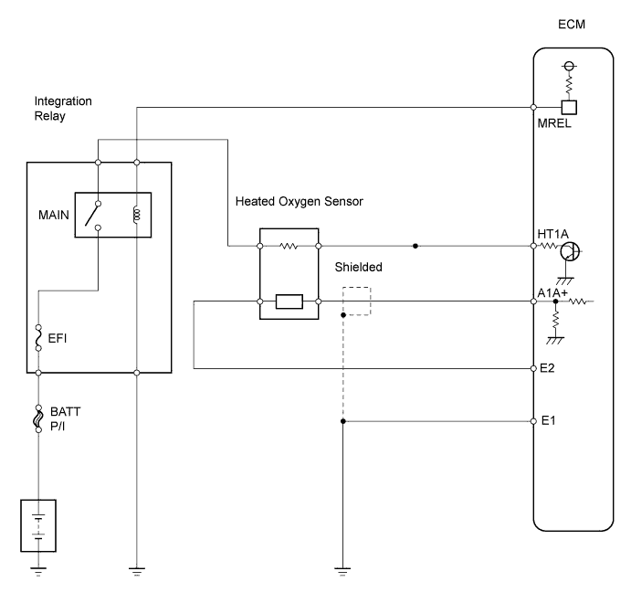
WIRING DIAGRAM
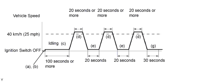
CONFIRMATION DRIVING PATTERN
-
(a) Connect the intelligent tester to the DLC3.
-
(b) Change the intelligent tester from the normal mode to the check (test) mode Click here.
-
(c) Start the engine and let the engine idle for 100 seconds or more.
-
(d) Drive the vehicle at 40 km/h (25 mph) or more for 20 seconds or more.
-
(e) Let the engine idle for 20 seconds or more.
-
(f) Perform steps (d) to (e) 3 times.
-
(g) Let the engine idle for 30 seconds or more.
Tech Tips
If a malfunction exists, the MIL will illuminate during step (g).
Note
If the conditions in this test are not strictly followed, detection of the malfunction will not be possible.
If you do not have an intelligent tester, turn the ignition switch OFF after performing steps (c) to (e), and then perform steps (c) to (e) again.
INSPECTION PROCEDURE
Tech Tips
Read freeze frame data using the intelligent tester. Freeze frame data records the engine conditions when malfunctions are detected. When troubleshooting, freeze frame data can help determine if the vehicle was moving or stationary, if the engine was warmed up or not, if the air-fuel ratio was lean or rich, and other data from the time the malfunction occurred.
When using intelligent tester:
PROCEDURE
-
CHECK OTHER DTC OUTPUT
-
Connect the intelligent tester to the DLC3.
-
Enter the following menus: Powertrain / Engine and ECT / DTC.
-
Read the DTCs.
Result DTC Proceed to Only P0130/21 is output A Other DTCs are output besides P0130/21 B Tech Tips
If any other codes besides P0130/21 are output, perform troubleshooting on those codes first.
B 
GO TO RELEVANT DTC CHART
A 
-
-
READ VALUE USING DATA LIST (OUTPUT VOLTAGE OF HEATED OXYGEN SENSOR)
-
Connect the intelligent tester to the DLC3.
-
Start the engine and turn the intelligent tester ON.
-
Enter the following menus: Powertrain / Engine and ECT / Data List / O2S B1 S1.
-
Warm up the heated oxygen sensor at an engine speed of 2,500 rpm for approximately 90 seconds.
-
Read the output voltage of the heated oxygen sensor during engine idling.
Standard Fluctuates between less than 0.4 V and more than 0.6 V (see the following figure). 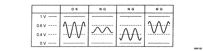
OK 
PERFORM CONFIRMATION DRIVING PATTERN Click here
NG
-
-
CHECK PCV HOSE
OK PCV hose is connected correctly, and is not damaged.
NG
CONNECT HOSE SECURELY OR REPLACE PCV HOSE
OK
-
INSPECT HEATED OXYGEN SENSOR
-
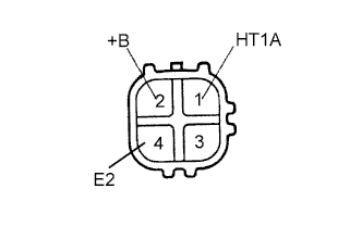
Disconnect the H9 sensor connector.
-
Measure the resistance of the sensor.
Standard resistance Tester Connection Condition Specified Condition 1 (HT1A) - 2 (+B) 20°C (68°F) 5 to 10 Ω 1 (HT1A) - 4 (E2) - 10 kΩ or higher
NG
REPLACE HEATED OXYGEN SENSOR
OK
-
-
INSPECT INTEGRATION NO.1 RELAY (MAIN RELAY)
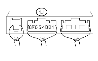
-
Remove the integration relay from the engine room junction block.
-
Measure the voltage of the MAIN relay.
Standard voltage Tester Connection Condition Specified Condition 1J-5 - Body ground Ignition switch ON 10 to 14 V
NG
REPLACE INTEGRATION NO.1 RELAY
OK
-
-
CHECK WIRE HARNESS (HEATED OXYGEN SENSOR - ECM)
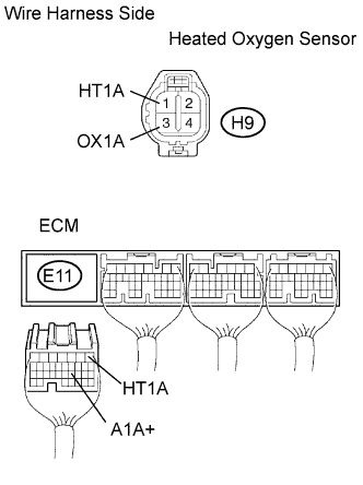
-
Disconnect the H9 heated oxygen sensor connector.
-
Disconnect the E11 ECM connector.
-
Measure the resistance of the wire harness side connectors.
Standard resistance Tester Connection Specified Condition H9-1 (HT1A) - E11-1 (HT1A)
H9-3 (OX1A) - E11-21 (A1A+)
Below 1 Ω H9-1 (HT1A) or E11-1 (HT1A) - Body ground
H9-3 (OX1A) or E11-21 (A1A+) - Body ground
10 kΩ or higher
NG
REPAIR OR REPLACE HARNESS AND CONNECTOR
OK
-
-
CHECK AIR INDUCTION SYSTEM
-
Check the air induction system for vacuum leakage.
OK No leakage from air induction system.
NG
REPAIR OR REPLACE AIR INDUCTION SYSTEM
OK
-
-
CHECK FUEL PRESSURE
-
Check the fuel pressure Click here.
NG
REPAIR OR REPLACE FUEL SYSTEM
OK
-
-
INSPECT FUEL INJECTOR ASSEMBLY
-
Check the fuel injector Click here.
NG
REPLACE FUEL INJECTOR ASSEMBLY
OK 
REPLACE HEATED OXYGEN SENSOR
-
-
PERFORM CONFIRMATION DRIVING PATTERN
Tech Tips
Clear all DTCs prior to performing the confirmation driving pattern.
NEXT
-
READ OUTPUT DTC
-
Read the DTC using the intelligent tester.
Result DTC Proceed to Only P0130/21 is output A Other DTCs are output besides P0130/21 B
B
CHECK FOR INTERMITTENT PROBLEMS
A
REPLACE HEATED OXYGEN SENSOR
-
When not using intelligent tester:
PROCEDURE
-
CHECK OTHER DTC OUTPUT
Result DTC Proceed to Only P0130/21 is output A Other DTCs are output besides P0130/21 B Tech Tips
If any other codes besides P0130/21 are output, perform troubleshooting on those codes first.
B
GO TO RELEVANT DTC CHART
A
-
CHECK WIRE HARNESS (HEATED OXYGEN SENSOR - ECM)
-
Disconnect the H9 heated oxygen sensor connector.
-
Disconnect the E11 ECM connector.
-
Measure the resistance of the wire harness side connectors.
Standard resistance Tester Connection Specified Condition H9-1 (HT1A) - E11-1 (HT1A)
H9-3 (OX1A) - E11-21 (A1A+)
Below 1 Ω H9-1 (HT1A) or E11-1 (HT1A) - Body ground
H9-3 (OX1A) or E11-21 (A1A+) - Body ground
10 kΩ or higher
NG
REPAIR OR REPLACE HARNESS AND CONNECTOR
OK
REPLACE HEATED OXYGEN SENSOR
-