SFI SYSTEM (w/ Secondary Air Injection System), Diagnostic DTC:P0500

| DTC Code | DTC Name |
|---|---|
| P0500 | Vehicle Speed Sensor "A" |
DESCRIPTION
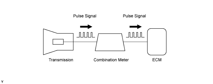
The vehicle speed sensor outputs 4 pulses for every revolution of the rotor shaft, which is rotated by the transmission output shaft via the driven gear. After this signal is converted into a more precise rectangular waveform by the waveform shaping circuit inside the combination meter, it is then transmitted to the ECM. The ECM determines the vehicle speed based on the frequency of this pulse signal.
| DTC No. | DTC Detection Condition | Trouble Area |
|---|---|---|
| P0500 | While the vehicle is being driven, no vehicle speed signal is input to the ECM (2 trip detection logic). |
|
MONITOR DESCRIPTION
-
The ECM assumes that the vehicle is being driven when the vehicle speed signal from the transmission (SP2) indicates a speed of 9 km/h (6 mph) or more.
If there is no vehicle speed signal from the combination meter (SP1) for 5 seconds when the vehicle is being driven, the ECM determines this to be a malfunction of the vehicle speed sensor. The ECM then illuminates the MIL and stores the DTC.
Automatic Transmission Models:
-
The ECM assumes that the vehicle is being driven when the indicated engine speed is 1500 to 4000 rpm and the engine load calculated by the ECM is more than a certain level. If there is no signal from the vehicle speed sensor, despite these conditions being met, the ECM interprets this as a malfunction in the speed signal circuit. The ECM then illuminates the MIL and stores the DTC.
-
The ECM assumes that the vehicle is being driven when the idle fuel-cut operation* is being executed. If there is no signal from the vehicle speed sensor despite this condition being met, the ECM interprets this as a malfunction in the speed signal circuit. The ECM then illuminates the MIL and stores the DTC.
*: Idle fuel-cut is executed when the throttle valve is fully closed and engine speed is over 2500 rpm.
Manual Transmission Models:
MONITOR STRATEGY
| Required Sensors/Components (Main) | Vehicle speed sensor, Combination meter assembly |
| Required Sensors/Components (Related) | Transmission revolution sensor (Speed sensor SP2), Engine coolant temperature sensor, Mass air flow meter, Crankshaft position sensor and Throttle position sensor |
| Frequency of Operation | Continuous |
TYPICAL ENABLING CONDITIONS
| Vehicle speed at Transmission revolution sensor (Speed sensor SP2) | 9 km/h (5.59 mph) or more |
| Either condition is met | A or B |
| A. Both conditions are met | 1 and 2 |
| 1. Engine speed | 1500 to 4000 rpm |
| 2. Engine load | 600% or more |
| B. Fuel-cut | ON |
TYPICAL MALFUNCTION THRESHOLDS
| Vehicle speed sensor signal | No pulse input |
CONFIRMATION DRIVING PATTERN
-
Connect the intelligent tester to the DLC3.
-
Turn the ignition switch to ON and turn the intelligent tester on.
-
Clear the DTCs (even if no DTCs are stored, perform the clear DTC operation).
-
Turn the ignition switch off and wait for at least 30 seconds.
-
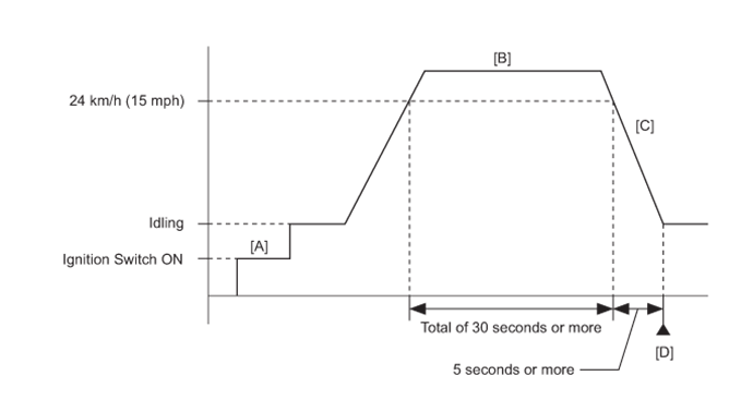
Turn the ignition switch to ON and turn the intelligent tester on [A].
-
Start the engine.
-
On the intelligent tester, enter the following menus to check the fuel-cut status: Powertrain / Engine and ECT / Data List / Idle Fuel Cut.
-
Drive the vehicle at 24 km/h (15 mph) or more for a total of 30 seconds or more [B].
-
Decelerate the vehicle by releasing the accelerator pedal for 5 seconds or more to perform the fuel-cut [C].
-
Stop the vehicle.
-
Enter the following menus: Powertrain / Engine and ECT / DTC [D].
-
Read the pending DTCs.
Tech Tips
-
If a pending DTC is output, the system is malfunctioning.
-
If a pending DTC is not output, perform the following procedure.
-
-
Enter the following menus: Powertrain / Engine and ECT / Utility / All Readiness.
-
Input the DTC: P0500.
-
Check the DTC judgment result.
Intelligent Tester Display Description NORMAL
-
DTC judgment completed
-
System normal
ABNORMAL
-
DTC judgment completed
-
System abnormal
INCOMPLETE
-
DTC judgment not completed
-
Perform driving pattern after confirming DTC enabling conditions
N/A
-
Unable to perform DTC judgment
-
Number of DTCs which do not fulfill DTC preconditions has reached ECU memory limit
Tech Tips
-
If the judgment result shows NORMAL, the system is normal.
-
If the judgment result shows ABNORMAL, the system has a malfunction.
-
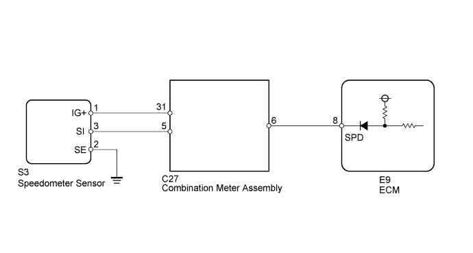
WIRING DIAGRAM
INSPECTION PROCEDURE
Tech Tips
Read freeze frame data using the intelligent tester. Freeze frame data records the engine condition when malfunctions are detected. When troubleshooting, freeze frame data can help determine if the vehicle was moving or stationary, if the engine was warmed up or not, if the air-fuel ratio was lean or rich, and other data from the time the malfunction occurred.
PROCEDURE
-
CHECK OPERATION OF SPEEDOMETER
-
Drive the vehicle and check whether the operation of the speedometer in the combination meter is normal.
Tech Tips
-
The vehicle speed sensor is operating normally if the speedometer reading is normal.
-
If the speedometer does not operate, check it by following the procedure described in Speedometer Malfunction.
-
NG 
GO TO MALFUNCTION IN SPEEDOMETER Click here
OK 
-
-
READ VALUE USING INTELLIGENT TESTER (VEHICLE SPEED)
-
Connect the intelligent tester to the DLC3.
-
Turn the ignition switch to ON.
-
Turn the tester on.
-
Enter the following menus: Powertrain / Engine and ECT / Data List / All Data / Vehicle Speed.
-
Drive the vehicle.
-
Read the value displayed on the tester.
OK Vehicle speeds displayed on tester and speedometer display are equal.
NG 
CHECK HARNESS AND CONNECTOR (COMBINATION METER - ECM) Click here
OK 
CHECK FOR INTERMITTENT PROBLEMS Click here
-
-
CHECK HARNESS AND CONNECTOR (COMBINATION METER - ECM)
-
Disconnect the combination meter connector.
-
Disconnect the ECM connector.
-
Measure the resistance according the value(s) in the table below.
Standard resistance Tester Connection Condition Specified Condition C27-6 - E9-8 (SPD) Always Below 1 Ω C27-6 or E9-8 (SPD) - Body ground Always 10 kΩ or higher Tech Tips
If the wire has a short, check the speed signal circuit in other systems related to the vehicle speed signal (e.g. tire pressure warning system, audio system, etc.).
NG
REPAIR OR REPLACE HARNESS OR CONNECTOR (OTHER SYSTEM RELATED TO SPEEDOMETER)
OK
-
-
CHECK COMBINATION METER ASSEMBLY (+S VOLTAGE)
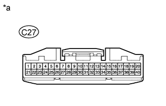
Text in Illustration *a Front view of wire harness connector
(to Combination Meter)
-
Disconnect the combination meter connector.
Tech Tips
Disconnect the ECU connectors on the other systems related to the speed signal (but the ECM connectors must be connected).
-
Turn the ignition switch to ON.
-
Measure the voltage according to the value(s) in the table below.
Standard voltage Tester Connection Condition Specified Condition C27-6 - Body ground Ignition switch on 4.5 to 5.5 V
NG
REPLACE ECM Click here
OK
-
-
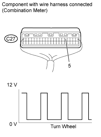
CHECK COMBINATION METER ASSEMBLY (SPD SIGNAL OUTPUT WAVEFORM)

-
Remove the combination meter assembly.
-
Connect the combination meter connector.
-
Move the shift lever to the neutral position.
-
Jack up one of the rear wheels.
-
Turn the ignition switch to ON.
-
Check the voltage between the terminal of the combination meter and the body ground while the rear wheel is turned slowly.
Standard voltage Tester Connection Condition Specified Condition C27-6 - Body ground Ignition switch on
Turn wheel slowly
Voltage generated intermittently Tech Tips
-
The output voltage should fluctuate up and down, similarly to the diagram, when the wheel is turned slowly.
-
A voltage of 12 V or 5 V is output from each ECU and then input to the combination meter assembly.
Tech Tips
The output voltage should fluctuate up and down, similarly to the diagram, when the wheel is turned slowly.
-
NG
CHECK COMBINATION METER ASSEMBLY (SPD SIGNAL INPUT WAVEFORM) Click here
OK
REPLACE ECM Click here
-
-
CHECK COMBINATION METER ASSEMBLY (SPD SIGNAL INPUT WAVEFORM)
-
Remove the combination meter assembly.
-
Connect the combination meter connector.
-
Move the shift lever to the neutral position.
-
Jack up one of the rear wheels.
-
Turn the ignition switch to ON.
-
Check the voltage between the terminal of the combination meter and the body ground while the rear wheel is turned slowly.
Standard voltage Tester Connection Condition Specified Condition C27-5 - Body ground Ignition switch on
Turn wheel slowly
Voltage generated intermittently Tech Tips
The output voltage should fluctuate up and down, similarly to the diagram, when the wheel is turned slowly.
NG
CHECK HARNESS AND CONNECTOR (COMBINATION METER - SPEEDOMETER SENSOR) Click here
OK
REPLACE COMBINATION METER ASSEMBLY Click here
-
-
CHECK HARNESS AND CONNECTOR (COMBINATION METER - SPEEDOMETER SENSOR)
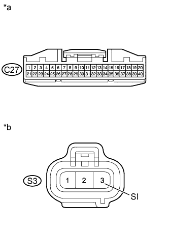
Text in Illustration *a Front view of wire harness connector
(to Combination Meter)
*b Front view of wire harness connector
(to Speedometer Sensor)
-
Disconnect the combination meter connector.
-
Disconnect the speedometer sensor connector.
-
Measure the resistance according to the value(s) in the table below.
Standard Resistance Tester Connection Condition Specified Condition C27-5 - S3-3 (SI) Always Below 1 Ω C27-5 or S3-3 (SI) - Body ground Always 10 kΩ or higher
NG
REPAIR OR REPLACE HARNESS OR CONNECTOR
OK
REPLACE SPEEDOMETER SENSOR
-