SFI SYSTEM ECM Power Source Circuit
DESCRIPTION
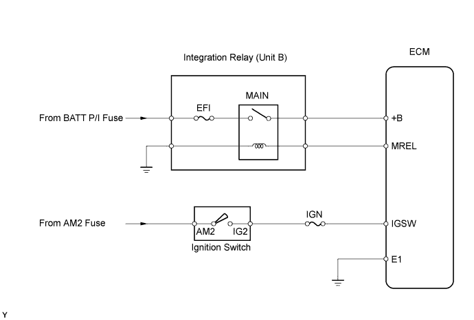
When the ignition switch is turned ON, battery voltage is applied to terminal IGSW of the ECM. The ECM "MREL" output signal causes a current to flow to the MAIN relay coil, closing the contacts of the MAIN relay and supplying power to terminal +B of the ECM.
WIRING DIAGRAM
INSPECTION PROCEDURE
PROCEDURE
-
CHECK ECM (+B VOLTAGE)
-
Turn the ignition switch ON.
-
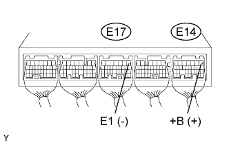
Measure the voltage of the ECM connectors.
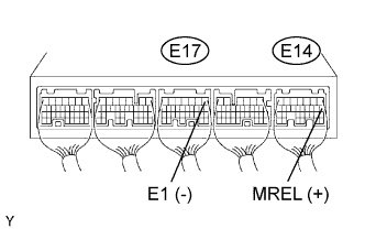
Standard voltage: Tester Connection Specified Condition E14-1 (+B) - E17-1 (E1) 9 to 14 V
OK 
PROCEED TO NEXT CIRCUIT INSPECTION SHOWN IN PROBLEM SYMPTOMS TABLE
NG 
-
-
CHECK WIRE HARNESS (ECM - BODY GROUND)
-
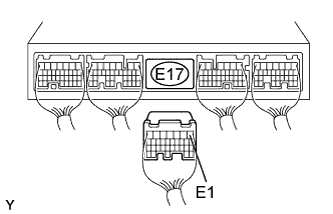
Disconnect the E17 ECM connector.
-
Measure the resistance of the wire harness side connector.
Standard resistance: Tester Connection Specified Condition E17-1 (E1) - Body ground Below 1 Ω
NG
REPAIR OR REPLACE HARNESS AND CONNECTOR
OK
-
-
CHECK ECM (IGSW VOLTAGE)
-
Turn the ignition switch ON.
-
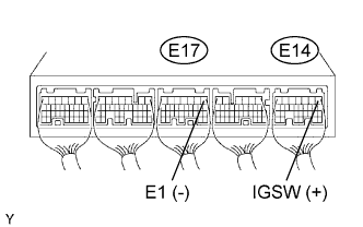
Measure the voltage of the ECM connectors.
Standard voltage Tester Connection Specified Condition E14-9 (IGSW) - E17-1 (E1) 9 to 14 V
OK 
CHECK ECM (MREL VOLTAGE) Click here
NG
-
-
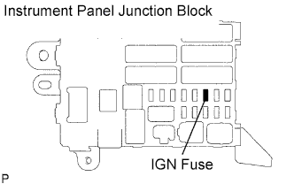
CHECK FUSE (IGN)
-
Remove the IGN fuse from the instrument panel junction block.
-
Measure the resistance of the fuse.
Standard resistance Below 1 Ω
NG
CHECK FOR SHORT IN ALL HARNESSES AND COMPONENTS CONNECTED TO FUSE
OK
-
-
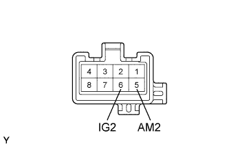
INSPECT IGNITION SWITCH ASSEMBLY
-
Disconnect the I6 ignition switch connector.
-
Measure the resistance of the switch.
Standard resistance: Tester Connection Switch Condition Specified Condition 5 (AM2) - 6 (IG2) LOCK 10 kΩ or higher 5 (AM2) - 6 (IG2) ON Below 1 Ω
NG
REPLACE IGNITION SWITCH ASSEMBLY
OK 
REPAIR OR REPLACE HARNESS AND CONNECTOR (BATTERY - IGNITION SWITCH, IGNITION SWITCH - ECM)
-
-
CHECK ECM (MREL VOLTAGE)
-
Turn the ignition switch ON.
-
Measure the voltage of the ECM connectors.
Standard voltage: Tester Connection Specified Condition E14-8 (MREL) - E17-1 (E1) 9 to 14 V
NG
REPLACE ECM
OK
-
-
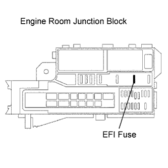
INSPECT FUSE (EFI)
-
Remove the EFI fuse from the engine room junction block.
-
Measure the resistance of the fuse.
Standard resistance Below 1 Ω
NG
CHECK FOR SHORT IN ALL HARNESSES AND COMPONENTS CONNECTED TO FUSE
OK
-
-
INSPECT INTEGRATION NO.1 RELAY (MAIN RELAY)
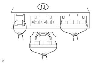
-
Disconnect the integration relay from the engine room junction block.
-
Measure the voltage of the integration relay.
Standard voltage: Tester Connection Condition Specified Condition 1J-4 - Body ground Ignition switch ON 10 to 14 V
NG
REPLACE INTEGRATION NO.1 RELAY
OK
-
-
CHECK WIRE HARNESS (INTEGRATION RELAY (MAIN RELAY) - ECM AND BODY GROUND)
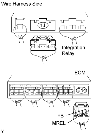
-
Disconnect the 1J integration relay connector from the engine room junction block.
-
Disconnect the E14 ECM connector.
-
Measure the resistance of the wire harness side connectors.
Standard resistance Tester Connection Specified Condition 1J-2 - E14-8 (MREL) Below 1 Ω 1J-4 - E14-1 (+B) Below 1 Ω 1J-3 - Body ground Below 1 Ω 1J-2 or E14-8 (MREL) - Body ground 10 kΩ or higher 1J-4 or E14-1 (+B) - Body ground 10 kΩ or higher
NG
REPAIR OR REPLACE HARNESS AND CONNECTOR
OK
REPAIR OR REPLACE HARNESS AND CONNECTOR (ECM - BATTERY POSITIVE TERMINAL)
-