SFI SYSTEM, Diagnostic DTC:P2238, P2239, P2241, P2242, P2252, P2253, P2255, P2256

| DTC Code | DTC Name |
|---|---|
| P2238 | Oxygen (A/F) Sensor Pumping Current Circuit Low (Bank 1 Sensor 1) |
| P2239 | Oxygen (A/F) Sensor Pumping Current Circuit High (Bank 1 Sensor 1) |
| P2241 | Oxygen (A/F) Sensor Pumping Current Circuit Low (Bank 2 Sensor 1) |
| P2242 | Oxygen (A/F) Sensor Pumping Current Circuit High (Bank 2 Sensor 1) |
| P2252 | Oxygen (A/F) Sensor Reference Ground Circuit Low (Bank 1 Sensor 1) |
| P2253 | Oxygen (A/F) Sensor Reference Ground Circuit High (Bank 1 Sensor 1) |
| P2255 | Oxygen (A/F) Sensor Reference Ground Circuit Low (Bank 2 Sensor 1) |
| P2256 | Oxygen (A/F) Sensor Reference Ground Circuit High (Bank 2 Sensor 1) |
DESCRIPTION
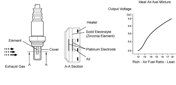
The Air Fuel Ratio (A/F) sensor generates voltage* in response to the actual air fuel ratio. This sensor output voltage provide feedback to the ECM. The ECM uses the feedback to control the air fuel ratio. Using the sensor output voltage, the ECM determines the deviation from the stoichiometric air fuel ratio, and regulates the injection time. If the A/F sensor is malfunctioning, the ECM is unable to control the air fuel ratio accurately. The A/F sensor is equipped with a heater which heats the zirconia element. The heater is also controlled by the ECM. When the intake air volume is low (the temperature of the exhaust gas is low), a current flows to the heater to heat the sensor to facilitate the detection of accurate oxygen concentration. The A/F sensor is a planar type. Compared to the conventional type, the sensor and heater portions are narrower. The heat of the heater is conducted to the zirconia element through the alumina, accelerating sensor activation. To obtain a high purification rate of carbon monoxide (CO), hydrocarbon (HC) and nitrogen oxide (NOx) in the exhaust gas, a Three-Way Catalytic Converter (TWC) is used. The TWC is most efficient when the air fuel ratio is maintained near the stoichiometric air fuel ratio.
Tech Tips
*: The voltage value changes inside the ECM only.
| DTC No. | DTC Detection Condition | Trouble Area |
|---|---|---|
| P2238 P2241 |
A/F sensor circuit low (bank 1 sensor 1) |
Tech Tips Main trouble area
|
| Condition (a) continues for 5.0 sec. or more: (a) A1A+ voltage is 0.5 V or less |
|
|
| Condition (a) continues for 5.0 sec. or more: (a) (A1A+) - (A1A-) = 0.1 V or less |
||
| P2239 P2242 |
A/F sensor circuit high (bank 1 sensor 1) (2 trip detection logic) |
Tech Tips Main trouble area
|
| Condition (a) continues for 5.0 sec. or more: (a) A1A+ voltage is greater than 4.5 V |
|
|
| Condition (a) continues for 5.0 sec. or more: (a) (A1A+) - (A1A-) = greater than 0.8 V |
||
| P2252 P2255 |
Condition (a) continues for 5.0 sec. or more: (a) A1A- voltage is 0.5 V or less (2 trip detection logic) |
|
| P2253 P2256 |
Condition (a) continues for 5.0 sec. or more: (a) A1A- voltage is greater than 4.5 V |
Tech Tips
-
DTCs P2238, P2239, P2252 and P2253 indicate malfunctions related to bank 1 A/F sensor circuit.
-
DTCs P2241, P2242, P2255 and P2256 indicate malfunctions related to bank 2 A/F sensor circuit.
-
Bank 1 refers to the bank that includes the No. 1 cylinder.
-
Bank 2 refers to the bank that includes the No. 2 cylinder.
MONITOR DESCRIPTION
The A/F sensor varies its output voltage in proportion to the air fuel ratio. If the A/F sensor impedance (alternating current resistance) or output voltage deviates greatly from the standard range, the ECM determines that there is an open or short malfunction in the A/F sensor circuit.
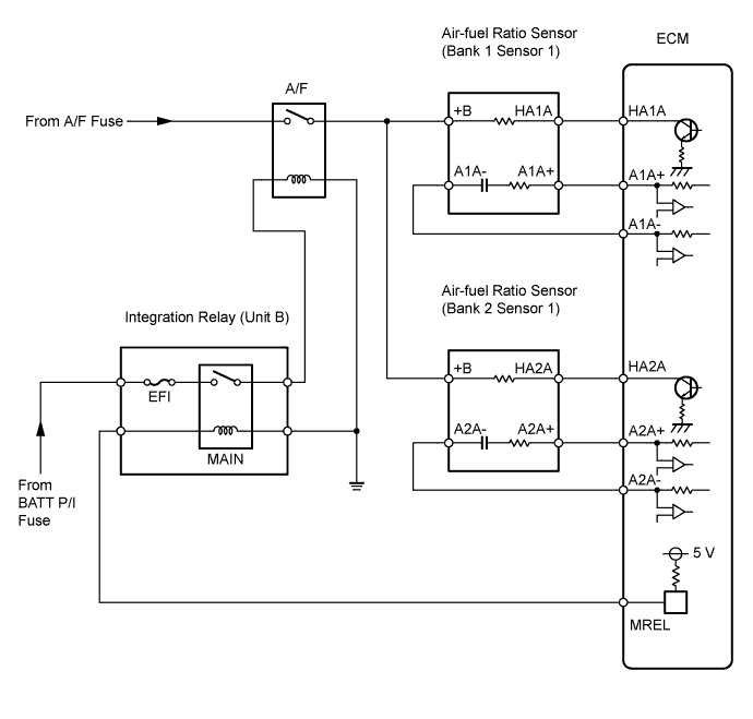
WIRING DIAGRAM
INSPECTION PROCEDURE
Tech Tips
Intelligent tester only:
Malfunctioning areas can be found by performing the Active Test "Control the injection volume for A/F sensor" operation. The "Control the injection volume for A/F sensor" operation can determine if the A/F sensor, heated oxygen sensor or other potential trouble areas are malfunctioning or not.
(a) Perform the Active Test using the intelligent tester.
Tech Tips
"Control the injection volume for A/F sensor" is an Active Test which changes the injection volume to -12.5% or +25%.
(1) Control the intelligent tester to the DLC3.
(2) Start the engine and turn the tester ON.
(3) Warm up the engine by running the engine at 2,500 rpm for approximately 90 seconds.
(4) Enter the following menus on the intelligent tester: Powertrain / Engine and ECT / Active Test / Control the injection volume for A/F sensor.
(5) Enter the following monitor items: AFS B1S1 and O2S B1S2 or AFS B2S1 and O2S B2S2.
(6) Perform the "Control the injection volume for A/F sensor" operation with the engine in an idling condition (press the right or left button).
Tech Tips
-
The "Control the injection volume for A/F sensor" operation lowers the fuel injection volume by 12.5% or increases the injection volume by 25%.
-
Each sensor reacts in accordance with increases and decreases in the fuel injection volume.
| Standard | ||||||||||||||||||||
|---|---|---|---|---|---|---|---|---|---|---|---|---|---|---|---|---|---|---|---|---|
|
Note
The A/F sensor output has a few seconds of delay and the heated oxygen sensor output has approximately 20 seconds of delay.
| Case | A/F Sensor (Sensor 1) Output Voltage |
Heated Oxygen Sensor (Sensor 2) Output Voltage |
Main Suspected Trouble Area | ||
|---|---|---|---|---|---|
| 1 | Injection volume +25% -12.5% |
 |
Injection volume +25% -12.5% |
|
- |
| Output voltage More than 3.35 V Less than 3.0 V |
 |
Output voltage More than 0.55 V Less than 0.4 V |
 |
||
| 2 | Injection volume +25% -12.5% |
|
Injection volume +25% -12.5% |
|
|
| Output voltage Almost no reaction |
 |
Output voltage More than 0.55 V Less than 0.4 V |
|
||
| 3 | Injection volume +25% -12.5% |
|
Injection volume +25% -12.5% |
|
|
| Output voltage More than 3.35 V Less than 3.0 V |
|
Output voltage Almost no reaction |
|
||
| 4 | Injection volume +25% -12.5% |
|
Injection volume +25% -12.5% |
|
|
| Output voltage Almost no reaction |
|
Output voltage Almost no reaction |
|
||
The following A/F control procedure enables technician to check and graph the output voltages of both the A/F sensor and heated oxygen sensor.
Tech Tips
-
Read freeze frame data using the intelligent tester. Freeze frame data records the engine conditions when a malfunction is detected. When troubleshooting, freeze frame data can help determine if the vehicle was running or stopped, if the engine was warmed up or not, if the air fuel ratio was lean or rich, and other data from the time the malfunction occurred.
-
These DTCs are related to the A/F sensor.
-
These DTCs are recorded when A/F sensor has a malfunction, although the caption is heated oxygen sensor.
PROCEDURE
-
INSPECT AIR FUEL RATIO SENSOR (HEATER RESISTANCE)
-
Disconnect the A30 and A31 A/F sensor connectors.
-
Measure the resistance of the A/F sensor.
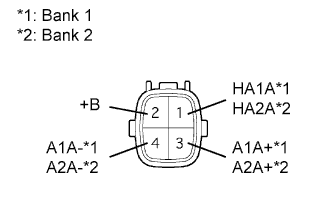
Standard resistance Bank 1 Sensor 1 Tester Connection Condition Specified Condition 1 (HA1A) - 2 (+B) 20°C (68°F) 1.8 to 3.4 Ω 1 (HA1A) - 4 (A1A-) - 10 kΩ or higher Bank 1 Sensor 1 Tester Connection Condition Specified Condition 1 (HA2A) - 2 (+B) 20°C (68°F) 1.8 to 3.4 Ω 1 (HA2A) - 4 (A2A-) - 10 kΩ or higher
NG 
REPLACE AIR FUEL RATIO SENSOR
OK 
-
-
INSPECT A/F RELAY (Marking: A/F)
-
Remove the relay from the engine room relay block.
-
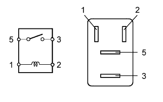
Measure the resistance of the relay.
Standard resistance Tester Connection Specified Condition 3 - 5 10 kΩ or higher 3 - 5 Below 1 Ω
(when battery voltage is applied to terminals 1 and 2)
NG
REPLACE A/F RELAY
OK
-
-
CHECK WIRE HARNESS (A/F SENSOR - ECM)
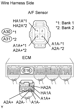
-
Disconnect the A30 and A31 A/F sensor connectors.
-
Disconnect the E16 ECM connector.
-
Measure the resistance of the wire harness side connectors.
Standard resistance Bank 1 Sensor 1 Tester Connection Specified Condition A30-1 (HA1A) - E16-2 (HA1A) Below 1 Ω A30-3 (A1A+) - E16-22 (A1A+) Below 1 Ω A30-4 (A1A-) - E16-30 (A1A-) Below 1 Ω A30-1 (HA1A) or E16-2 (HA1A) - Body ground 10 kΩ or higher A30-3 (A1A+) or E16-22 (A1A+) - Body ground 10 kΩ or higher A30-4 (A1A-) or E16-30 (A1A-) - Body ground 10 kΩ or higher Bank 2 Sensor 1 Tester Connection Specified Condition A31-1 (HA2A) - E16-1 (HA2A) Below 1 Ω A31-3 (A2A) - E16-23 (A2A+) Below 1 Ω A31-4 (A2A-) - E16-31 (A2A-) Below 1 Ω A31-1 (HA2A) or E16-1 (HA2A) - Body ground 10 kΩ or higher A31-3 (A2A+) or E16-23 (A2A+) - Body ground 10 kΩ or higher A31-4 (A2A-) or E16-31 (A2A-) - Body ground 10 kΩ or higher
NG
REPAIR OR REPLACE HARNESS AND CONNECTOR
OK 
REPLACE ECM
-