SFI SYSTEM, Diagnostic DTC:P0443

| DTC Code | DTC Name |
|---|---|
| P0443 | Evaporative Emission Control System Purge Control Valve Circuit |
DESCRIPTION
In order to reduce Hydrocarbon (HC) emissions, evaporated fuel from the fuel tank is routed through the charcoal canister to the intake manifold for combustion in the cylinders.
The ECM changes the duty signal to the purge VSV so that the intake of HC emissions is appropriate for the driving conditions (engine load, engine speed, vehicle speed, etc.) after the engine is warmed up.
| DTC No. | DTC Detection Condition | Trouble Area |
|---|---|---|
| P0443 | Proper response to ECM command does not occur (1 trip detection logic) |
|
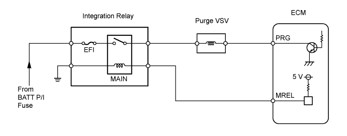
WIRING DIAGRAM
INSPECTION PROCEDURE
Tech Tips
Read freeze frame data using the intelligent tester. Freeze frame data records the engine conditions when a malfunction is detected. When troubleshooting, freeze frame data can help determine if the vehicle was running or stopped, if the engine was warmed up or not, if the air fuel ratio was lean or rich, and other data from the time the malfunction occurred.
PROCEDURE
-
PERFORM ACTIVE TEST USING INTELLIGENT TESTER (PURGE VSV)
-
Disconnect the vacuum hose from the purge VSV.
-
Connect the intelligent tester to the DLC3.
-
Enter the engine and turn the intelligent tester ON.
-
Enter the following menus: Powertrain / Engine and ECT / Active Test / Activate the VSV for EVAP Control. Press the right or left button.
-
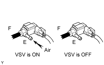
Place a finger on port E. Check if the disconnected port applies suction to your finger when operating the purge VSV using the intelligent tester.
Standard Tester Operation Specified Condition VSV is ON Applies suction to your finger VSV is OFF Applies no suction to your finger
OK 
CHECK FOR INTERMITTENT PROBLEMS
NG 
-
-
CHECK ECM (PRG VOLTAGE)
-
Turn the ignition switch ON.
-
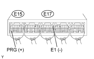
Measure the voltage of the E15 and E17 ECM connectors.
Standard voltage Tester Connection Specified Condition E15-34 (PRG) - E17-1 (E1) 9 to 14 V
OK
REPLACE ECM
NG
-
-
INSPECT PURGE VSV
OK Air flows when battery voltage is applied to purge VSV.
NG
REPLACE PURGE VSV
OK
-
CHECK WIRE HARNESS (ECM - PURGE VSV)
-
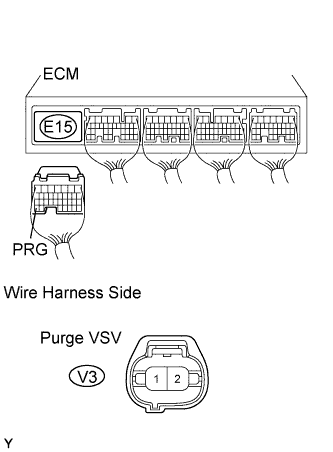
Disconnect the E15 connector.
-
Disconnect the V3 purge VSV connector.
-
Measure the resistance of the wire harness side connectors.
Standard resistance Tester Connection Specified Condition V3-2 - E15-34 (PRG) Below 1 Ω V3-2 or E15-34 (PRG) - Body ground 10 kΩ or higher
NG
REPAIR OR REPLACE HARNESS AND CONNECTOR
OK
-
-
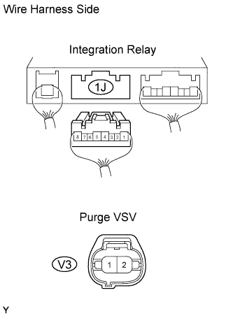
CHECK WIRE HARNESS (INTEGRATION RELAY - PURGE VSV)
-
Disconnect the 1J integration relay connector from the engine room junction block.
-
Disconnect the V3 purge VSV connector.
-
Measure the resistance of the wire harness side connectors.
Standard resistance Tester Connection Specified Condition V3-1 - 1J-5 Below 1 Ω V3-1 or 1J-5 - Body ground 10 kΩ or higher
NG
REPAIR OR REPLACE HARNESS AND CONNECTOR
OK 
INSPECT ECM POWER SOURCE CIRCUIT
-