SFI SYSTEM, Diagnostic DTC:P0500

| DTC Code | DTC Name |
|---|---|
| P0500 | Vehicle Speed Sensor Malfunction |
DESCRIPTION
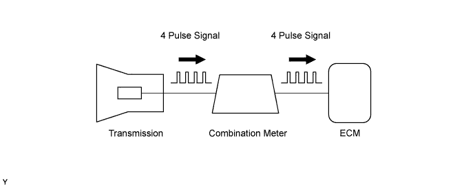
The vehicle speed sensor outputs a 4 pulse signal for every revolution of the rotor shaft, which is rotated by the transmission output shaft via the driven gear. After this signal is converted into a more precise rectangular waveform by the waveform shaping circuit inside the combination meter, it is then transmitted to the ECM. The ECM determines the vehicle speed based on the frequency of these pulse signals.
| DTC No. | DTC Detection Condition | Trouble Area |
|---|---|---|
| P0500 | While vehicle is being driven, no vehicle speed sensor signal input to ECM (2 trip detection logic) |
|
MONITOR DESCRIPTION
The ECM assumes that the vehicle is being driven when the engine speed is more than 2,000 rpm and the Park/Neutral Position (PNP) switch has been OFF for 30 seconds. If there is no signal from the vehicle speed sensor when the vehicle is being driven, the ECM interprets this as a malfunction in the vehicle speed sensor.
The ECM illuminates the Malfunction Indicator Lamp (MIL) and sets the DTC.
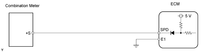
WIRING DIAGRAM
INSPECTION PROCEDURE
Tech Tips
Read freeze frame data using the intelligent tester. Freeze frame data records the engine conditions when a malfunction is detected. When troubleshooting, freeze frame data can help determine if the vehicle was running or stopped, if the engine was warmed up or not, if the air fuel ratio was lean or rich, and other data from the time the malfunction occurred.
PROCEDURE
-
CHECK COMBINATION METER (OPERATION OF SPEEDOMETER)
-
Drive the vehicle. Check that the speedometer operation is normal.
OK Speedometer operation is normal. Tech Tips
The vehicle speed sensor is operating normally if the speedometer reading is normal.
NG 
CHECK SPEEDOMETER CIRCUIT
OK 
-
-
CHECK ECM (SPD VOLTAGE)
-
Move the shift lever to the neutral position.
-
Jack up one of the rear wheels.
-
Turn the ignition switch ON.
-
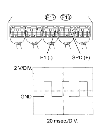
Turn the rear wheel slowly, and measure the voltage of the ECM connectors.
OK Tester Connection Specified Condition E13- 8 (SPD) - E17-1 (E1) Correct waveform is as shown Tool Setting Condition 2 V/DIV., 20 msec./DIV. Driving at 20 km/h (12 mph) Tech Tips
The output voltage should fluctuate up and down (as shown in the illustration) when the wheel is turned slowly.
OK
REPLACE ECM
NG
-
-
CHECK WIRE HARNESS (COMBINATION METER ASSEMBLY - ECM)
-
Disconnect the C27 combination meter connector.
-
Disconnect the E13 ECM connector.
-
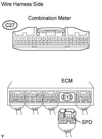
Measure the resistance of the wire harness side connectors.
Standard resistance Tester Connection Specified Condition C27-6 - E13-8 (SPD) Below 1 Ω C27-6 or E13-8 (SPD) - Body ground 10 kΩ or higher
NG
REPAIR OR REPLACE HARNESS AND CONNECTOR
OK 
REPLACE COMBINATION METER ASSEMBLY
-