SFI SYSTEM, Diagnostic DTC:P0340, P0342, P0343, P0345, P0347, P0348

| DTC Code | DTC Name |
|---|---|
| P0340 | Camshaft Position Sensor Circuit Malfunction |
| P0342 | Camshaft Position Sensor "A" Circuit Low Input (Bank 1 or Single Sensor) |
| P0343 | Camshaft Position Sensor "A" Circuit High Input (Bank 1 or Single Sensor) |
| P0345 | Camshaft Position Sensor "A" Circuit (Bank 2) |
| P0347 | Camshaft Position Sensor "A" Circuit Low Input (Bank 2) |
| P0348 | Camshaft Position Sensor "A" Circuit High Input (Bank 2) |
DESCRIPTION
The camshaft position sensor (G) signal consists of a magnet and MRE element.
The camshaft drive gear has 3 teeth on its inner circumference. When the camshaft gear rotates, changes occur in the air gaps between the protrusion on the gear and the pickup coil. The change affects the magnetic field and results in changes in the resistance of the MRE element. The crankshaft angle sensor plate has 34 teeth and outputs 34 signals every engine revolution. The ECM detects the standard crankshaft angle based on the G signal, and actual crankshaft angle and engine speed based on the crankshaft position sensor (NE) signal.
| DTC No. | DTC Detection Condition | Trouble Area |
|---|---|---|
| P0340 P0345 |
STA ON: No camshaft position sensor signal to ECM during cranking for 4 seconds or more STA OFF: No camshaft position sensor signal to ECM with engine speed 600 or more |
|
| P0342 P0347 |
Output voltage of Variable Valve Timing (VVT) sensor 0.3 V or less for 5 seconds (1 trip detection logic) |
|
| P0343 P0348 |
Output voltage of VVT sensor 4.7 V or more for 5 seconds (1 trip detection logic) |
|
WIRING DIAGRAM
Refer to DTC P0335 Click here.
INSPECTION PROCEDURE
Tech Tips
Read freeze frame data using the intelligent tester. Freeze frame data records the engine conditions when a malfunction is detected. When troubleshooting, freeze frame data can help determine if the vehicle was running or stopped, if the engine was warmed up or not, if the air fuel ratio was lean or rich, and other data from the time the malfunction occurred.
PROCEDURE
-
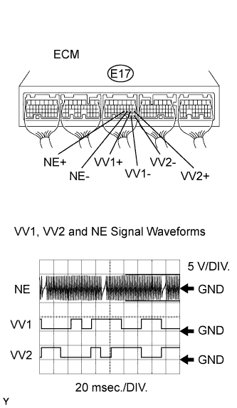
CHECK ECM (VV1, VV2, NE WAVEFORM)
-
Inspect using an oscilloscope.
-
While the engine is idling, check the waveform of the ECM connector.
OK Tester Connection Specified Condition E17-19 (VV1+) - E17-29 (VV1-)
E17-18 (VV2+) - E17-28 (VV2-)
E17-21 (NE+) - E17-20 (NE-)
Correct waveform is as shown Tool Setting Condition 5 V/DIV., 20 msec./DIV. Idling
-
NG 
REPLACE VVT SENSOR
OK 
-
-
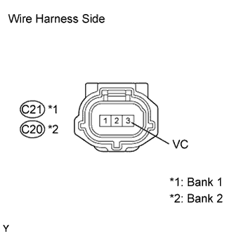
CHECK WIRE HARNESS (SENSOR POWER SOURCE)
-
Disconnect the C20 and C21 VVT sensor connectors.
-
Turn the ignition switch ON.
-
Measure the voltage of the wire harness side connectors.
Standard voltage Tester Connection Specified Condition C20-3 (VC) - Body ground 4.5 to 5.5 V C21-3 (VC) - Body ground 4.5 to 5.5 V
NG
REPAIR OR REPLACE HARNESS AND CONNECTOR
OK
-
-
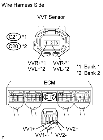
CHECK WIRE HARNESS (VVT SENSOR - ECM)
-
Disconnect the C20 and C21 VVT sensor connectors.
-
Disconnect the E17 ECM connector.
-
Measure the resistance of the wire harness side connectors.
Standard resistance Bank 1 Tester Connection Specified Condition C21-1 (VVR+) - E17-19 (VV1+) Below 1 Ω C21-2 (VVR-) - E17-29 (VV1-) Below 1 Ω C21-1 (VVR+) or E17-19 (VV1+) - Body ground 10 kΩ or higher C21-2 (VVR-) or E17-29 (VV1-) - Body ground 10 kΩ or higher Bank 2 Tester Connection Specified Condition C20-1 (VVL+) - E17-18 (VV2+) Below 1 Ω C20-2 (VVL-) - E17-28 (VV2-) Below 1 Ω C20-1 (VVL+) or E17-18 (VV2+) - Body ground 10 kΩ or higher C20-2 (VVL-) or E17-28 (VV2-) - Body ground 10 kΩ or higher
NG
REPAIR OR REPLACE HARNESS AND CONNECTOR
OK
-
-
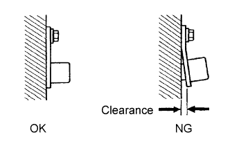
CHECK VVT SENSOR (INSTALLATION)
-
Check the VVT sensor installation.
OK Sensor is installed correctly.
NG
SECURELY REINSTALL VVT SENSOR
OK
-
-
CHECK CAMSHAFT TIMING GEAR ASSEMBLY (TEETH OF PLATE)
-
Check the teeth of the signal plate.
OK Signal plate does not have cracks or deformation.
NG
REPLACE CAMSHAFT TIMING GEAR ASSEMBLY
OK 
REPLACE VVT SENSOR
-