SFI SYSTEM, Diagnostic DTC:P0230

| DTC Code | DTC Name |
|---|---|
| P0230 | Fuel Pump Primary Circuit |
DESCRIPTION
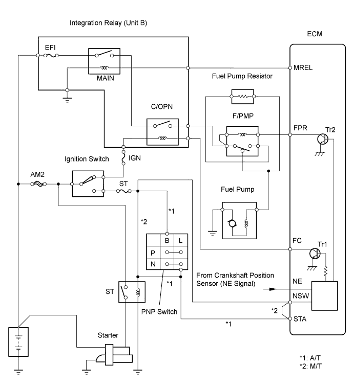
When the engine is cranked, current flows from terminal ST2 of the ignition switch to the ST relay coil and also current flows to terminal STA of the ECM (STA signal). When the STA signal and NE signal are input to the ECM, Transistor 1 (Tr1) of the ECM is turned ON, current flows to the coil of the circuit opening relay (Unit B: C/OPN), the relay switches on, power is supplied to the fuel pump, and the fuel pump operates.
While the NE signal is generated (engine running), the ECM keeps Tr1 ON (C/OPN relay ON) and the fuel pump also keeps operating. The fuel pump speed is controlled at two levels (high speed or low speed) by the condition of the engine (starting, light load, heavy load).
The fuel pump operates at high speed when: 1) the engine starts and the STA signal is ON: and 2) Transistor 2 (Tr2) of the ECM is OFF, causing the fuel pump relay (Marking: F/PMP) to close and battery positive (+) voltage to be applied directly to the fuel pump.
The fuel pump operates at low speed when: 1) after the engine starts, the engine is idling or has a light load: and 2) since the ECM's Tr2 is ON, battery positive voltage is applied to the fuel pump via the fuel pump resistor.
| DTC No. | DTC Detection Condition | Trouble Area |
|---|---|---|
| P0230 | Open or short in fuel pump relay circuit for 0.5 second or more (1 trip detection logic) |
|
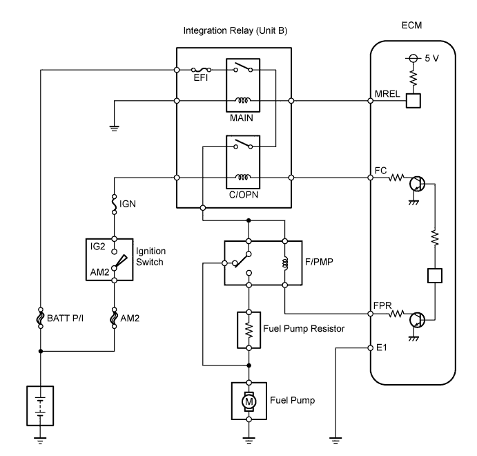
WIRING DIAGRAM
Tech Tips
This DTC chart is based on the premise that the engine is started normally. If the engine is difficult to start, proceed to the problem symptoms table Click here.
INSPECTION PROCEDURE
Tech Tips
Read freeze frame data using the intelligent tester. Freeze frame data records the engine conditions when a malfunction is detected. When troubleshooting, freeze frame data can help determine if the vehicle was running or stopped, if the engine was warmed up or not, if the air fuel ratio was lean or rich, and other data from the time the malfunction occurred.
PROCEDURE
-
CHECK ECM (FPR VOLTAGE)
-
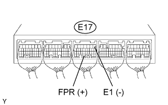
Measure the voltage of the ECM connectors.
Standard voltage Tester Connection Condition Specified Condition E17-30 (FPR) - E17-1 (E1) STA signal ON 9 to 14 V E17-30 (FPR) - E17-1 (E1) STA signal OFF 0 to 3 V
NG 
REPLACE ECM
OK 
-
-
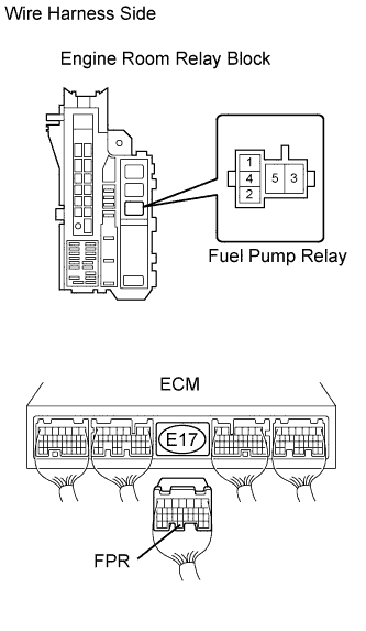
INSPECT FUEL PUMP RELAY (Marking: F/PMP)
-
Remove the relay from the engine room relay block.
-
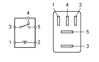
Measure the resistance the relay.
Standard resistance Tester Connection Specified Condition 3 - 4 Below 1 Ω 3 - 5 10 kΩ or higher 3 - 4 10 kΩ or higher
(when battery voltage is applied to terminals 1 and 2)
3 - 5 Below 1 Ω
(when battery voltage is applied to terminals 1 and 2)
NG
REPLACE FUEL PUMP RELAY
OK
-
-
CHECK WIRE HARNESS (FUEL PUMP RELAY (Marking: F/PMP) - ECM)
-
Remove the fuel pump relay from the engine room relay block.
-
Disconnect the E17 ECM connector.
-
Measure the resistance of the wire harness side connectors.
Standard resistance Tester Connection Specified Condition Relay block fuel pump relay terminal 1 - E17-30 (FPR) Below 1 Ω Relay block fuel pump relay terminal 1 or E17-30 (FPR) - Body ground 10 kΩ or higher
NG
REPAIR OR REPLACE HARNESS AND CONNECTOR
OK 
REPLACE ECM
-