SFI SYSTEM, Diagnostic DTC:P0037, P0038, P0057, P0058

| DTC Code | DTC Name |
|---|---|
| P0037 | Oxygen Sensor Heater Control Circuit Low (Bank 1 Sensor 2) |
| P0038 | Oxygen Sensor Heater Control Circuit High (Bank 1 Sensor 2) |
| P0057 | Oxygen Sensor Heater Control Circuit Low (Bank 2 Sensor 2) |
| P0058 | Oxygen Sensor Heater Control Circuit High (Bank 2 Sensor 2) |
DESCRIPTION
-
Refer to DTC P0136 Click here.
Tech Tips
-
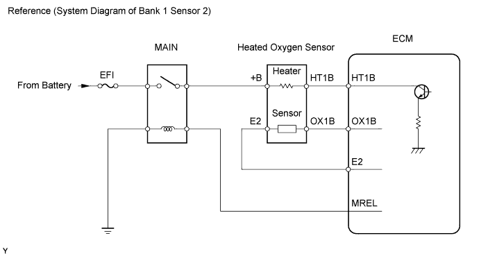
When any of these DTCs are set, the ECM enters fail-safe mode. The ECM turns off the heated oxygen sensor (HO2S) heater in fail-safe mode. Fail-safe mode continues until the ignition switch is turned OFF.
-
The ECM uses a pulse width modulated control circuit to adjust current through the heater. The heated oxygen sensor heater circuit uses a relay on the +B side of the circuit.
| DTC No. | DTC Detection Condition | Trouble Area |
|---|---|---|
| P0037 P0057 |
Heated oxygen sensor (HO2S) heater current less than 0.3 A (1 trip detection logic) |
|
| P0038 P0058 |
Heated oxygen sensor (HO2S) heater current more than 2 A (1 trip detection logic) |
|
Tech Tips
-
Bank 1 refers to the bank that includes the No. 1 cylinder.
-
Bank 2 refers to the bank that does not include the No. 1 cylinder.
-
Sensor 1 refers to the sensor closer to the engine assembly.
-
Sensor 2 refers to the sensor farther away from the engine assembly.
MONITOR DESCRIPTION
-
The sensing portion of the heated oxygen sensor has a zirconia element which is used to detect oxygen concentration in the exhaust. If the zirconia element is at the appropriate temperature and the difference of the oxygen concentrations between the inside and outside surface of the sensor is large, the zirconia element will generate voltage signals. In order to increase the oxygen concentration detecting capacity of the zirconia element, the ECM supplements the heat from the exhaust with the heat from the heating element inside the sensor. When the current in the sensor is out of the standard operating range, the ECM interprets this as a fault in the heated oxygen sensor heater and sets a DTC.
-
Example:
-
The ECM will set a high current DTC if the current in the sensor is more than 2 A when the heater is OFF. Similarly, the ECM will set a low current DTC if the current is less than 0.3 A when the heater is ON.
WIRING DIAGRAM
Refer to DTC P0136 Click here.
INSPECTION PROCEDURE
Tech Tips
-
Read freeze frame data using the intelligent tester. Freeze frame data records the engine conditions when a malfunction is detected. When troubleshooting, freeze frame data can help determine if the vehicle was running or stopped, if the engine was warmed up or not, if the air fuel ratio was lean or rich, and other data, from the time the malfunction occurred.
-
Sensor 1 refers to the sensor mounted before the Three-Way Catalytic Converter (TWC) and is located near the engine assembly.
-
Sensor 2 refers to the sensor mounted after the TWC and is located far from the engine assembly.
PROCEDURE
-
INSPECT HEATED OXYGEN SENSOR (HEATER RESISTANCE)
-
Disconnect the H12 and H13 heated oxygen sensor connectors.
-
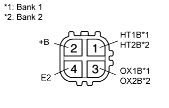
Measure the resistance of the sensor.
Standard resistance Bank 1 Tester Connection Condition Specified Condition 1 (HT1B) - 2 (+B) 20°C (68°F) 11 to 16 Ω 1 (HT1B) - 4 (E2) - 10 kΩ or higher Bank 2 Tester Connection Condition Specified Condition 1 (HT2B) - 2 (+B) 20°C (68°F) 11 to 16 Ω 1 (HT2B) - 4 (E2) - 10 kΩ or higher
NG 
REPLACE HEATED OXYGEN SENSOR
OK 
-
-
INSPECT INTEGRATION NO.1 RELAY (MAIN RELAY)
-
Disconnect the integration relay from the engine room junction block.
-
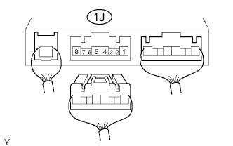
Measure the voltage of the MAIN relay.
Standard resistance Tester Connection Condition Specified Condition 1J-5 - Body ground Ignition switch ON 10 to 14 V
NG
REPLACE INTEGRATION NO.1 RELAY
OK
-
-
CHECK ECM (HT1B, HT2B VOLTAGE)
-
Turn the ignition switch ON.
-
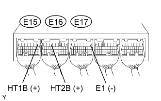
Measure the voltage of the ECM connector.
Standard voltage Tester Connection Specified Condition E15-1 (HT1B) - E17-1 (E1) 9 to 14 V E16-5 (HT2B) - E17-1 (E1) 9 to 14 V
OK
REPLACE ECM
NG
-
-
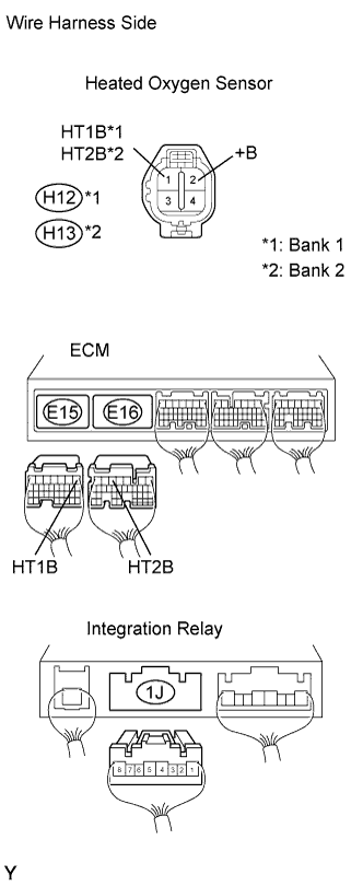
CHECK WIRE HARNESS (HEATED OXYGEN SENSOR - ECM AND INTEGRATION RELAY (MAIN RELAY))
-
Disconnect the H12 or H13 sensor connectors.
-
Disconnect the E15 or E16 ECM connector.
-
Disconnect the 1J connector from the engine room junction block.
-
Measure the resistance of the wire harness side connectors.
Standard resistance Bank 1 Sensor 2 Tester Connection Specified Condition H12-1 (HT1B) - E15-1 (HT1B) Below 1 Ω H12-2 (+B) - 1J-5 Below 1 Ω H12-1 (HT1B) or E15-1 (HT1B) - Body ground 10 kΩ or higher H12-2 (+B) or 1J-5 - Body ground 10 kΩ or higher Bank 2 Sensor 2 Tester Connection Specified Condition H13-1 (HT2B) - E16-5 (HT2B) Below 1 Ω H13-2 (+B) - 1J-5 Below 1 Ω H13-1 (HT2B) or E16-5 (HT2B) - Body ground 10 kΩ or higher H13-2 (+B) or 1J-5 - Body ground 10 kΩ or higher
NG
REPAIR OR REPLACE HARNESS AND CONNECTOR
OK 
REPLACE ECM
-