LIGHTING SYSTEM Back-up Light Circuit
DESCRIPTION
The hybrid vehicle control ECU controls the back-up lights via the BKUP LP relay.
WIRING DIAGRAM
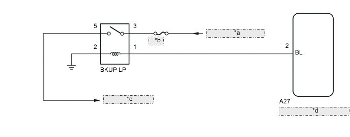
| *a | from IG1 NO. 1 Relay |
| *b | GAUGE |
| *c | to Back-up Lights |
| *d | Hybrid Vehicle Control ECU |
CAUTION / NOTICE / HINT
Note
Inspect the fuses and bulbs for circuits related to this system before performing the following inspection procedure.
PROCEDURE
-
CHECK DTC OUTPUT (HYBRID CONTROL SYSTEM)
-
Check for DTCs Click here.
OK Hybrid control system DTCs are not output.
NG 
GO TO HYBRID CONTROL SYSTEM Click here
OK 
-
-
INSPECT BACK UP LIGHT RELAY (BKUP LP RELAY)
-
Inspect the back up light relay (BKUP LP relay) Click here.
NG
REPLACE BACK UP LIGHT RELAY (BKUP LP RELAY)
OK
-
-
CHECK HARNESS AND CONNECTOR (BACK UP LIGHT RELAY - IG1 NO. 1 RELAY AND BODY GROUND)
-
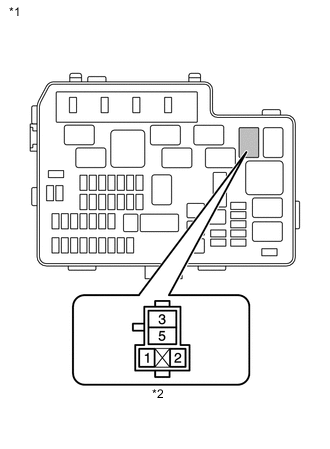
Text in Illustration *1 No. 2 Engine Room Relay Block *2 Back Up Light Relay (BKUP LP Relay) Holder Remove the back up light relay (BKUP LP relay) from the No. 2 engine room relay block.
-
Measure the voltage according to the value(s) in the table below.
Standard Voltage Tester Connection Switch Condition Specified Condition 3 - Body ground Ignition switch ON (IG) 11 to 14 V -
Measure the resistance according to the value(s) in the table below.
Standard Resistance Tester Connection Condition Specified Condition 2 - Body ground Always Below 1 Ω
NG
REPAIR OR REPLACE HARNESS OR CONNECTOR
OK
-
-
CHECK HARNESS AND CONNECTOR (BACK UP LIGHT RELAY - HYBRID VEHICLE CONTROL ECU)
-
Remove the back up light relay (BKUP LP relay) from the No. 2 engine room relay block.
-
Disconnect the A27 hybrid vehicle control ECU connector.
-
Measure the resistance according to the value(s) in the table below.
Standard Resistance Tester Connection Condition Specified Condition Relay terminal 1 - A27-2 (BL) Always Below 1 Ω Relay terminal 1 - Body ground Always 10 kΩ or higher
OK
REPLACE HYBRID VEHICLE CONTROL ECU Click here
NG
REPAIR OR REPLACE HARNESS OR CONNECTOR
-