LIGHTING SYSTEM Hazard Warning Switch Circuit
DESCRIPTION
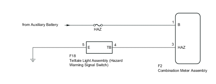
The combination meter assembly receives information signals from the telltale light assembly (hazard warning signal switch).
WIRING DIAGRAM
CAUTION / NOTICE / HINT
Note
Inspect the fuses for circuits related to this system before performing the following inspection procedure.
PROCEDURE
-
READ VALUE USING GTS
-
Connect the GTS to the DLC3.
-
Turn the ignition switch to ON (IG).
-
Turn the GTS on.
-
Enter the following menus: Body Electrical / Combination Meter / Data List.
-
According to the display on the GTS, read the Data List.
Combination Meter Tester Display Measurement Item/Range Normal Condition Diagnostic Note Hazard Flasher Switch Hazard warning signal switch /
OFF or ON
OFF: Hazard warning signal switch off
ON: Hazard warning signal switch on
- OK Normal conditions listed above are displayed.
OK 
PROCEED TO NEXT SUSPECTED AREA SHOWN IN PROBLEM SYMPTOMS TABLE Click here
NG 
-
-
INSPECT TELLTALE LIGHT ASSEMBLY (HAZARD WARNING SIGNAL SWITCH)
-
Inspect the telltale light assembly (hazard warning signal switch) Click here.
NG
REPLACE TELLTALE LIGHT ASSEMBLY (HAZARD WARNING SIGNAL SWITCH) Click here
OK
-
-
CHECK HARNESS AND CONNECTOR (COMBINATION METER ASSEMBLY - AUXILIARY BATTERY)
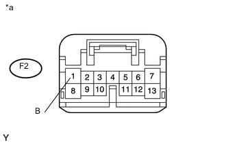
Text in Illustration *a Front view of wire harness connector
(to Combination Meter Assembly)
-
Disconnect the combination meter assembly connector.
-
Measure the voltage according to the value(s) in the table below.
Standard Voltage Tester Connection Condition Specified Condition F2-1 (B) - Body Ground Always 11 to 14 V
NG
REPAIR OR REPLACE HARNESS OR CONNECTOR
OK
-
-
CHECK HARNESS AND CONNECTOR (TELLTALE LIGHT ASSEMBLY (HAZARD WARNING SIGNAL SWITCH) - COMBINATION METER ASSEMBLY)
-
Disconnect the F18 telltale light assembly (hazard warning signal switch) connector.
-
Disconnect the F2 combination meter assembly connector.
-
Measure the resistance according to the value(s) in the table below.
Standard Resistance Tester Connection Condition Specified Condition F18-4 (TB) - F2-3 (HAZ) Always Below 1 Ω F18-5 (E) - Body Ground Always Below 1 Ω F18-4 (TB) - Body ground Always 10 kΩ or higher
OK
REPLACE COMBINATION METER ASSEMBLY Click here
NG
REPAIR OR REPLACE HARNESS OR CONNECTOR
-