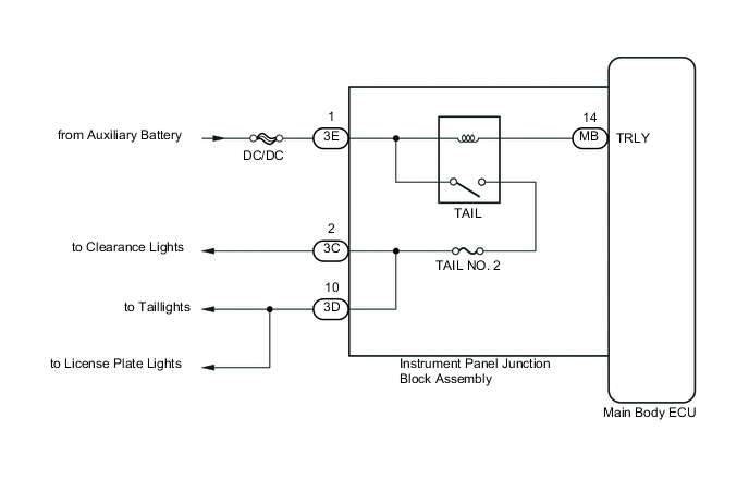
LIGHTING SYSTEM Taillight Relay Circuit
DESCRIPTION
The main body ECU controls the TAIL relay.
WIRING DIAGRAM
CAUTION / NOTICE / HINT
Note
Inspect the fuses for circuits related to this system before performing the following inspection procedure.
PROCEDURE
-
PERFORM ACTIVE TEST USING GTS
-
Connect the GTS to the DLC3.
-
Turn the ignition switch to ON (IG).
-
Turn the GTS on.
-
Enter the following menus: Body Electrical / Main Body / Active Test.
-
According to the display on the GTS, perform the Active Test.
Main Body Tester Display Test Part Control Range Diagnostic Note Taillight Relay Taillight relay OFF or ON - OK TAIL relay operates. (Clearance lights, taillights and license plate lights illuminate.)
OK 
PROCEED TO NEXT SUSPECTED AREA SHOWN IN PROBLEM SYMPTOMS TABLE Click here
NG 
-
-
CHECK HARNESS AND CONNECTOR (INSTRUMENT PANEL JUNCTION BLOCK ASSEMBLY - AUXILIARY BATTERY)
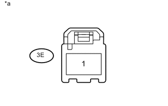
Text in Illustration *a Front view of wire harness connector
(to Instrument Panel Junction Block Assembly)
-
Disconnect the 3E instrument panel junction block assembly connector.
-
Measure the voltage according to the value(s) in the table below.
Standard Voltage Tester Connection Condition Specified Condition 3E-1 - Body ground Always 11 to 14 V
NG
REPAIR OR REPLACE HARNESS OR CONNECTOR
OK
-
-
REPLACE MAIN BODY ECU
-
Replace the main body ECU Click here.
NEXT
-
-
PERFORM ACTIVE TEST USING GTS
-
Connect the GTS to the DLC3.
-
Turn the ignition switch to ON (IG).
-
Turn the GTS on.
-
Enter the following menus: Body Electrical / Main Body / Active Test.
-
According to the display on the GTS, perform the Active Test.
Main Body Tester Display Test Part Control Range Diagnostic Note Taillight Relay Taillight relay OFF or ON - OK TAIL relay operates. (Clearance lights, taillights and license plate lights illuminate.)
OK
END (MAIN BODY ECU WAS DEFECTIVE)
NG
REPLACE INSTRUMENT PANEL JUNCTION BLOCK ASSEMBLY
-