POWER WINDOW CONTROL SYSTEM Rear Power Window LH does not Operate with Rear Power Window Switch LH
DESCRIPTION
If the rear LH side manual UP / DOWN function does not operate, a malfunction may exist in the rear door window regulator assembly LH, rear power window regulator switch assembly LH, power window regulator master switch assembly or wire harness.
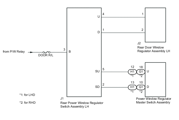
WIRING DIAGRAM
CAUTION / NOTICE / HINT
Note
Inspect the fuses for circuits related to this system before performing the following inspection procedure.
PROCEDURE
-
INSPECT REAR POWER WINDOW REGULATOR SWITCH ASSEMBLY LH
-
Inspect the rear power window regulator switch assembly LH Click here.
NG 
REPLACE REAR POWER WINDOW REGULATOR SWITCH ASSEMBLY LH Click here
OK 
-
-
INSPECT REAR DOOR WINDOW REGULATOR ASSEMBLY LH
-
Inspect rear door window regulator assembly LH
-
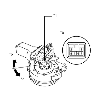
Text in Illustration *1 Motor Gear *a Component without harness connected
(Rear Door Window Regulator Assembly LH)
*b Clockwise *c Counterclockwise Apply auxiliary battery voltage to the regulator motor and check the operation of the regulator motor.
OK Measurement Condition Specified Condition Auxiliary battery positive (+) → 1
Auxiliary battery negative (-) → 2
Motor gear rotates clockwise Auxiliary battery positive (+) → 2
Auxiliary battery negative (-) → 1
Motor gear rotates counterclockwise If the result is not as specified, replace the rear door window regulator assembly LH.
-
NG
REPLACE REAR DOOR WINDOW REGULATOR ASSEMBLY LH Click here
OK
-
-
CHECK HARNESS AND CONNECTOR (REAR POWER WINDOW REGULATOR SWITCH ASSEMBLY LH - P/W RELAY)
-
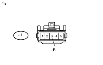
Text in Illustration *a Front view of wire harness connector
(to Rear Power Window Regulator Switch Assembly LH)
Disconnect the rear power window regulator switch assembly LH connector.
-
Measure the voltage according to the value(s) in the table below.
Standard Voltage Tester Connection Switch Condition Specified Condition J1-3 (B) - Body ground Ignition switch ON (IG) 11 to 14 V
NG
REPAIR OR REPLACE HARNESS OR CONNECTOR
OK
-
-
CHECK HARNESS AND CONNECTOR (REAR POWER WINDOW REGULATOR SWITCH ASSEMBLY LH - REAR DOOR WINDOW REGULATOR ASSEMBLY LH)
-
Disconnect the J1 rear power window regulator switch assembly LH connector.
-
Disconnect the J2 rear door window regulator assembly LH connector.
-
Measure the resistance according the value(s) in the table below.
Standard Resistance Tester Connection Condition Specified Condition J1-4 (U) - J2-1 (U) Always Below 1 Ω J1-1 (D) - J2-2 (D) Always Below 1 Ω J1-4 (U) - Body ground Always 10 kΩ or higher J1-1 (D) - Body ground Always 10 kΩ or higher
NG
REPAIR OR REPLACE HARNESS OR CONNECTOR
OK
-
-
CHECK HARNESS AND CONNECTOR (REAR POWER WINDOW REGULATOR SWITCH ASSEMBLY LH - POWER WINDOW REGULATOR MASTER SWITCH ASSEMBLY)
-
for LHD
-
Disconnect the J1 rear power window regulator switch assembly LH connector.
-
Disconnect the H1 power window regulator master switch assembly connector.
-
Measure the resistance according to the value(s) in the table below.
Standard Resistance Tester Connection Condition Specified Condition J1-5 (SU) - H1-12 (U) Always Below 1 Ω J1-2 (SD) - H1-13 (D) Always Below 1 Ω J1-5 (SU) - Body ground Always 10 kΩ or higher J1-2 (SD) - Body ground Always 10 kΩ or higher
-
-
for RHD
-
Disconnect the J1 rear power window regulator switch assembly LH connector.
-
Disconnect the G1 power window regulator master switch assembly connector.
-
Measure the resistance according to the value(s) in the table below.
Standard resistance Tester Connection Condition Specified Condition J1-5 (SU) - G1-18 (U) Always Below 1 Ω J1-2 (SD) - G1-10 (D) Always Below 1 Ω J1-5 (SU) - Body ground Always 10 kΩ or higher J1-2 (SD) - Body ground Always 10 kΩ or higher
-
OK
REPLACE POWER WINDOW REGULATOR MASTER SWITCH ASSEMBLY Click here
NG
REPAIR OR REPLACE HARNESS OR CONNECTOR
-