POWER WINDOW CONTROL SYSTEM Front Passenger Side Power Window does not Operate with Front Passenger Side Power Window Switch
DESCRIPTION
If the passenger side manual UP / DOWN function does not operate, a malfunction may exist in the front door window regulator assembly (front passenger side), power window regulator switch assembly (front passenger side), power window regulator master switch assembly or wire harness.
WIRING DIAGRAM
CAUTION / NOTICE / HINT
Note
Inspect the fuses for circuits related to this system before performing the following inspection procedure.
PROCEDURE
-
INSPECT POWER WINDOW REGULATOR SWITCH ASSEMBLY (FRONT PASSENGER SIDE)
-
Inspect the power window regulator switch assembly (front passenger side) Click here.
NG 
REPLACE POWER WINDOW REGULATOR SWITCH ASSEMBLY (FRONT PASSENGER SIDE) Click here
OK 
-
-
INSPECT FRONT DOOR WINDOW REGULATOR ASSEMBLY (FRONT PASSENGER SIDE)
-
Inspect front door window regulator assembly (front passenger side)
-
Apply auxiliary battery voltage to the motor connector according to the table below.
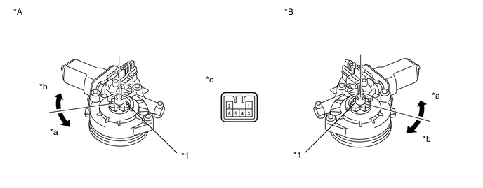
Text in Illustration *A for LHD *B for RHD *1 Motor Gear - - *a Counterclockwise *b Clockwise *c Component without harness connected
(Front Door Window Regulator Assembly (Front Passenger Side))
- - OK Measurement Condition Specified Condition Auxiliary battery positive (+) → 1
Auxiliary battery negative (-) → 2
Motor gear rotates clockwise Auxiliary battery positive (+) → 2
Auxiliary battery negative (-) → 1
Motor gear rotates counterclockwise If the result is not as specified, replace the front door window regulator assembly (front passenger side).
-
NG
REPLACE FRONT DOOR WINDOW REGULATOR ASSEMBLY (FRONT PASSENGER SIDE) Click here
OK
-
-
CHECK HARNESS AND CONNECTOR (POWER WINDOW REGULATOR SWITCH ASSEMBLY - P/W RELAY)
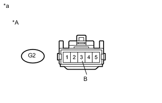
Text in Illustration *A for LHD *a Front view of wire harness connector
(to Power Window Regulator Switch Assembly (Front Passenger Side))
-
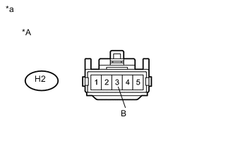
Text in Illustration *A for RHD *a Front view of wire harness connector
(to Power Window Regulator Switch Assembly (Front Passenger Side))
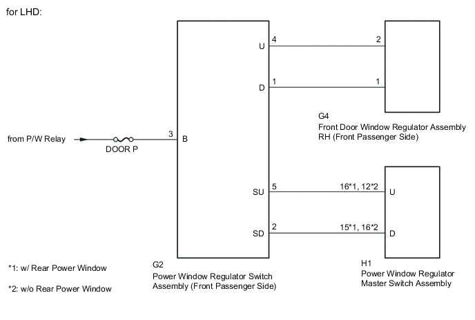
for LHD
-
Disconnect the power window regulator switch assembly (front passenger side) connector.
-
Measure the voltage according to the value(s) in the table below.
Standard Voltage Tester Connection Switch Condition Specified Condition G2-3 (B) - Body ground Ignition switch ON (IG) 11 to 14 V
-
-
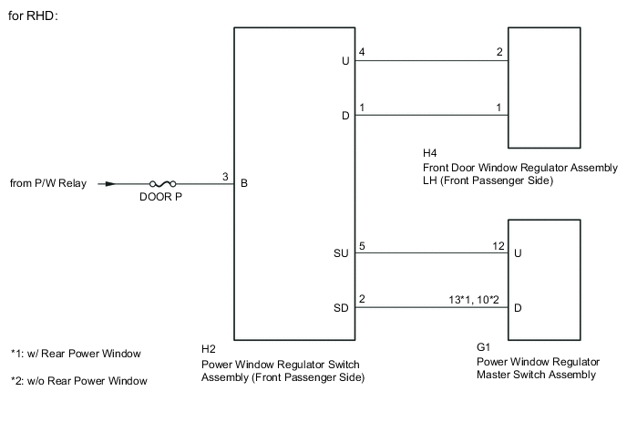
for RHD
-
Disconnect the power window regulator switch assembly (front passenger side) connector.
-
Measure the voltage according to the value(s) in the table below.
Standard Voltage Tester Connection Switch Condition Specified Condition H2-3 (B) - Body ground Ignition switch ON (IG) 11 to 14 V
-
NG
REPAIR OR REPLACE HARNESS OR CONNECTOR
OK
-
-
CHECK HARNESS AND CONNECTOR (POWER WINDOW REGULATOR SWITCH ASSEMBLY - FRONT DOOR WINDOW REGULATOR ASSEMBLY)
-
for LHD
-
Disconnect the G2 power window regulator switch assembly (front passenger side) connector.
-
Disconnect the G4 front door window regulator assembly RH (front passenger side) connector.
-
Measure the resistance according to the value(s) in the table below.
Standard Resistance Tester Connection Condition Specified Condition G2-4 (U) - G4-2 Always Below 1 Ω G2-1 (D) - G4-1 Always Below 1 Ω G2-4 (U) - Body ground Always 10 kΩ or higher G2-1 (D) - Body ground Always 10 kΩ or higher
-
-
for RHD
-
Disconnect the H2 power window regulator switch assembly (front passenger side) connector.
-
Disconnect the H4 front door window regulator assembly LH (front passenger side) connector.
-
Measure the resistance according to the value(s) in the table below.
Standard Resistance Tester Connection Condition Specified Condition H2-4 (U) - H4-2 Always Below 1 Ω H2-1 (D) - H4-1 Always Below 1 Ω H2-4 (U) - Body ground Always 10 kΩ or higher H2-1 (D) - Body ground Always 10 kΩ or higher
-
NG
REPAIR OR REPLACE HARNESS OR CONNECTOR
OK
-
-
CHECK HARNESS AND CONNECTOR (POWER WINDOW REGULATOR SWITCH ASSEMBLY - POWER WINDOW REGULATOR MASTER SWITCH ASSEMBLY)
-
for LHD
-
Disconnect the G2 power window regulator switch assembly (front passenger side) connector.
-
Disconnect the H1 power window regulator master switch assembly connector.
-
Measure the resistance according to the value(s) in the table below.
Standard Resistance w/ Rear Power Window Tester Connection Condition Specified Condition G2-5 (SU) - H1-16 (U) Always Below 1 Ω G2-2 (SD) - H1-15 (D) Always Below 1 Ω G2-5 (SU) - Body ground Always 10 kΩ or higher G2-2 (SD) - Body ground Always 10 kΩ or higher w/o Rear Power Window Tester Connection Condition Specified Condition G2-5 (SU) - H1-12 (U) Always Below 1 Ω G2-2 (SD) - H1-16 (D) Always Below 1 Ω G2-5 (SU) - Body ground Always 10 kΩ or higher G2-2 (SD) - Body ground Always 10 kΩ or higher
-
-
for RHD
-
Disconnect the H2 power window regulator switch assembly (front passenger side) connector.
-
Disconnect the G1 power window regulator master switch assembly connector.
-
Measure the resistance according to the value(s) in the table below.
Standard Resistance w/ Rear Power Window Tester Connection Condition Specified Condition H2-5 (SU) - G1-12 (U) Always Below 1 Ω H2-2 (SD) - G1-13 (D) Always Below 1 Ω H2-5 (SU) - Body ground Always 10 kΩ or higher H2-2 (SD) - Body ground Always 10 kΩ or higher w/o Rear Power Window Tester Connection Condition Specified Condition H2-5 (SU) - G1-12 (U) Always Below 1 Ω H2-2 (SD) - G1-10 (D) Always Below 1 Ω H2-5 (SU) - Body ground Always 10 kΩ or higher H2-2 (SD) - Body ground Always 10 kΩ or higher
-
OK
REPLACE POWER WINDOW REGULATOR MASTER SWITCH ASSEMBLY Click here
NG
REPAIR OR REPLACE HARNESS OR CONNECTOR
-