POWER WINDOW CONTROL SYSTEM Driver Side Power Window does not Operate with Power Window Master Switch
DESCRIPTION
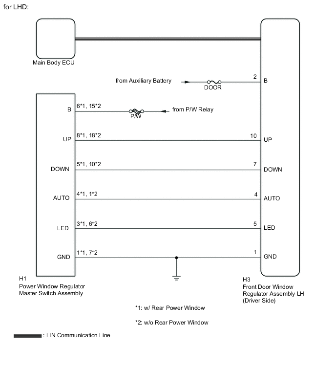
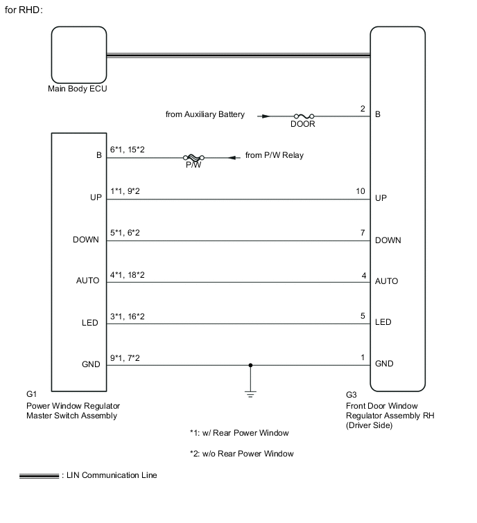
When the engine is running or the ignition switch is ON (IG), the front door window regulator assembly (driver side) is operated by the power window regulator master switch assembly. The front door window regulator assembly (driver side) has motor, regulator and ECU functions.
WIRING DIAGRAM
CAUTION / NOTICE / HINT
Note
-
The power window control system uses a LIN communication system. Inspect the communication function by following How to Proceed with Troubleshooting Click here. Troubleshoot the power window control system after confirming that the communication system is functioning properly.
-
When the front door window regulator assembly (driver side) is reinstalled or replaced, the power window control system must be initialized.
-
After a door glass or a door glass run has been replaced, the jam protection function may operate unexpectedly when the auto up function is used. In such cases, the auto up function can be resumed by repeating the following operations at least 5 times:
-
Close the power window by fully pulling up the power window regulator master switch assembly and holding it in the auto up position.
-
Open the power window by fully pushing down the power window regulator master switch assembly.
-
Inspect the fuses for circuits related to this system before performing the following inspection procedure.
PROCEDURE
-
READ VALUE USING GTS
-
Connect the GTS to the DLC3.
-
Turn the ignition switch to ON (IG).
-
Turn the GTS on.
-
Enter the following menus: Body Electrical / D-Door Motor / Data List.
-
According to the display on the GTS, perform the Data List.
D-Door Motor Tester Display Measurement Item/Range Normal Condition Diagnostic Note D Door P/W Auto SW Driver side power window auto switch signal /
ON or OFF
ON: Driver side door power window auto switch operated
OFF: Driver side door power window auto switch not operated
- D Door P/W Up SW Driver side power window manual up switch signal /
ON or OFF
ON: Driver side door power window manual up switch operated
OFF: Driver side door power window manual up switch not operated
- D Door P/W Down SW Driver side power window manual down switch signal /
ON or OFF
ON: Driver side door power window manual down switch operated
OFF: Driver side door power window manual down switch not operated
- OK Normal conditions listed above are displayed.
NG 
INSPECT POWER WINDOW REGULATOR MASTER SWITCH ASSEMBLY Click here
OK 
-
-
PERFORM ACTIVE TEST USING GTS
-
Connect the GTS to the DLC3.
-
Turn the ignition switch to ON (IG).
-
Turn the GTS on.
-
Enter the following menus: Body Electrical / D-Door Motor / Active Test.
-
According to the display on the GTS, perform the Active Test.
CAUTION:
Be careful to avoid injuries as this test causes vehicle parts to move. During the Active Test, the jam protection function will not operate.
D-Door Motor Tester Display Test Part Control Range Diagnostic Note Power Window Power window OFF / DOWN / UP - OK Driver side door power window operates normally.
OK 
REPLACE MAIN BODY ECU Click here
NG
REPLACE FRONT DOOR WINDOW REGULATOR ASSEMBLY (DRIVER SIDE) Click here
-
-
INSPECT POWER WINDOW REGULATOR MASTER SWITCH ASSEMBLY
-
Inspect the power window regulator master switch assembly Click here.
NG
REPLACE POWER WINDOW REGULATOR MASTER SWITCH ASSEMBLY Click here
OK
-
-
CHECK HARNESS AND CONNECTOR (POWER WINDOW REGULATOR MASTER SWITCH ASSEMBLY - P/W RELAY AND BODY GROUND)
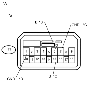
Text in Illustration *A for LHD *B w/ Rear Power Window *C w/o Rear Power Window *a Front view of wire harness connector
(to Power Window Regulator Master Switch Assembly)
-
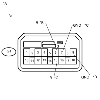
Text in Illustration *A for RHD *B w/ Rear Power Window *C w/o Rear Power Window *a Front view of wire harness connector
(to Power Window Regulator Master Switch Assembly)
for LHD
-
Disconnect the power window regulator master switch assembly connector.
-
Measure the voltage according to the value(s) in the table below.
Standard Voltage w/ Rear Power Window Tester Connection Switch Condition Specified Condition H1-6 (B) - Body ground Ignition switch ON (IG) 11 to 14 V w/o Rear Power Window Tester Connection Switch Condition Specified Condition H1-15 (B) - Body ground Ignition switch ON (IG) 11 to 14 V -
Measure the resistance according to the value(s) in the table below.
Standard Resistance w/ Rear Power Window Tester Connection Condition Specified Condition H1-1 (GND) - Body ground Always Below 1 Ω w/o Rear Power Window Tester Connection Condition Specified Condition H1-7 (GND) - Body ground Always Below 1 Ω
-
-
for RHD
-
Disconnect the power window regulator master switch assembly connector.
-
Measure the voltage according to the value(s) in the table below.
Standard Voltage w/ Rear Power Window Tester Connection Switch Condition Specified Condition G1-6 (B) - Body ground Ignition switch ON (IG) 11 to 14 V w/o Rear Power Window Tester Connection Switch Condition Specified Condition G1-15 (B) - Body ground Ignition switch ON (IG) 11 to 14 V -
Measure the resistance according to the value(s) in the table below.
Standard Resistance w/ Rear Power Window Tester Connection Condition Specified Condition G1-9 (GND) - Body ground Always Below 1 Ω w/o Rear Power Window Tester Connection Condition Specified Condition G1-7 (GND) - Body ground Always Below 1 Ω
-
NG
REPAIR OR REPLACE HARNESS OR CONNECTOR
OK
-
-
CHECK HARNESS AND CONNECTOR (FRONT DOOR WINDOW REGULATOR ASSEMBLY (DRIVER SIDE) - AUXILIARY BATTERY AND BODY GROUND)
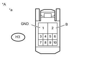
Text in Illustration *A for LHD *a Front view of wire harness connector
(to Front Door Window Regulator Assembly LH (Driver Side))
-
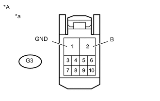
Text in Illustration *A for RHD *a Front view of wire harness connector
(to Front Door Window Regulator Assembly RH (Driver Side))
for LHD
-
Disconnect the front door window regulator assembly LH (driver side) connector.
-
Measure the voltage according to the value(s) in the table below.
Standard Voltage Tester Connection Condition Specified Condition H3-2 (B) - Body ground Always 11 to 14 V -
Measure the resistance according to the value(s) in the table below.
Standard Resistance Tester Connection Condition Specified Condition H3-1 (GND) - Body ground Always Below 1 Ω
-
-
for RHD
-
Disconnect the front door window regulator assembly RH (driver side) connector.
-
Measure the voltage according to the value(s) in the table below.
Standard Voltage Tester Connection Condition Specified Condition G3-2 (B) - Body ground Always 11 to 14 V -
Measure the resistance according to the value(s) in the table below.
Standard Resistance Tester Connection Condition Specified Condition G3-1 (GND) - Body ground Always Below 1 Ω
-
NG
REPAIR OR REPLACE HARNESS OR CONNECTOR
OK
-
-
CHECK HARNESS AND CONNECTOR (POWER WINDOW REGULATOR MASTER SWITCH ASSEMBLY - FRONT DOOR WINDOW REGULATOR ASSEMBLY)
-
for LHD
-
Disconnect the H1 power window regulator master switch assembly connector.
-
Disconnect the H3 front door window regulator assembly LH (driver side) connector.
-
Measure the resistance according to the value(s) in the table below.
Standard Resistance w/ Rear Power Window Tester Connection Condition Specified Condition H1-8 (UP) - H3-10 (UP) Always Below 1 Ω H1-5 (DOWN) - H3-7 (DOWN) Always Below 1 Ω H1-4 (AUTO) - H3-4 (AUTO) Always Below 1 Ω H1-3 (LED) - H3-5 (LED) Always Below 1 Ω H1-8 (UP) - Body ground Always 10 kΩ or higher H1-5 (DOWN) - Body ground Always 10 kΩ or higher H1-4 (AUTO) - Body ground Always 10 kΩ or higher H1-3 (LED) - Body ground Always 10 kΩ or higher w/o Rear Power Window Tester Connection Condition Specified Condition H1-18 (UP) - H3-10 (UP) Always Below 1 Ω H1-10 (DOWN) - H3-7 (DOWN) Always Below 1 Ω H1-1 (AUTO) - H3-4 (AUTO) Always Below 1 Ω H1-6 (LED) - H3-5 (LED) Always Below 1 Ω H1-18 (UP) - Body ground Always 10 kΩ or higher H1-10 (DOWN) - Body ground Always 10 kΩ or higher H1-1 (AUTO) - Body ground Always 10 kΩ or higher H1-6 (LED) - Body ground Always 10 kΩ or higher
-
-
for RHD
-
Disconnect the G1 power window regulator master switch assembly connector.
-
Disconnect the G3 front door window regulator assembly RH (driver side) connector.
-
Measure the resistance according to the value(s) in the table below.
Standard Resistance w/ Rear Power Window Tester Connection Condition Specified Condition G1-1 (UP) - G3-10 (UP) Always Below 1 Ω G1-5 (DOWN) - G3-7 (DOWN) Always Below 1 Ω G1-4 (AUTO) - G3-4 (AUTO) Always Below 1 Ω G1-3 (LED) - G3-5 (LED) Always Below 1 Ω G1-1 (UP) - Body ground Always 10 kΩ or higher G1-5 (DOWN) - Body ground Always 10 kΩ or higher G1-4 (AUTO) - Body ground Always 10 kΩ or higher G1-3 (LED) - Body ground Always 10 kΩ or higher w/o Rear Power Window Tester Connection Condition Specified Condition G1-9 (UP) - G3-10 (UP) Always Below 1 Ω G1-6 (DOWN) - G3-7 (DOWN) Always Below 1 Ω G1-18 (AUTO) - G3-4 (AUTO) Always Below 1 Ω G1-16 (LED) - G3-5 (LED) Always Below 1 Ω G1-9 (UP) - Body ground Always 10 kΩ or higher G1-6 (DOWN) - Body ground Always 10 kΩ or higher G1-18 (AUTO) - Body ground Always 10 kΩ or higher G1-16 (LED) - Body ground Always 10 kΩ or higher
-
OK
REPLACE FRONT DOOR WINDOW REGULATOR ASSEMBLY (DRIVER SIDE) Click here
NG
REPAIR OR REPLACE HARNESS OR CONNECTOR
-