LOWER INSTRUMENT PANEL REASSEMBLY
PROCEDURE
-
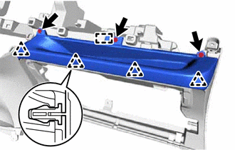
INSTALL NO. 1 SWITCH HOLE BASE (for RHD)
-
Engage the 5 clips and install the No. 1 switch hole base.
-
-
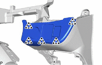
INSTALL NO. 1 INSTRUMENT PANEL BOX
-
Engage the guide and 4 clips.
-
Install the No. 1 instrument panel box with the 3 <A> screws.
-
-
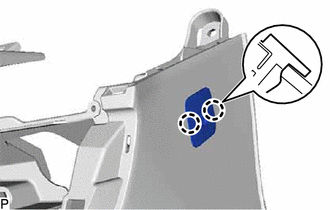
INSTALL GLOVE COMPARTMENT DOOR STOPPER SUB-ASSEMBLY
-
Engage the claw to install the glove compartment door stopper sub-assembly.
-
-
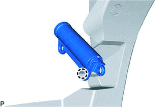
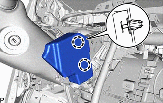
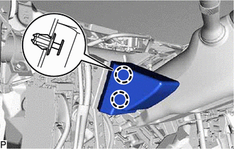
INSTALL AIRBAG CUT OFF SWITCH CYLINDER SUB-ASSEMBLY
-
Engage the 2 claws to install the airbag cut off switch cylinder sub-assembly.
-
-
INSTALL SPARE SWITCH HOLE COVER
-
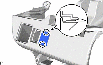
Engage the 2 claws to install the spare switch hole cover.
-
-
INSTALL HEADLIGHT LEVELING SWITCH (w/o Cover)
-
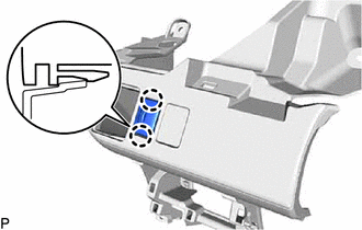
Engage the 2 claws to install the light control rheostat.
-
-
INSTALL SPARE SWITCH HOLE COVER (w/ Cover)
-
Engage the 2 claws to install the spare switch hole cover.
-
-
INSTALL OUTER MIRROR SWITCH ASSEMBLY (w/o Cover)
-
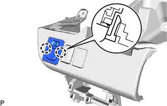
Engage the 2 claws to install the outer mirror switch assembly.
-
-
INSTALL REMOTE CONTROL MIRROR HOLE COVER (w/ Cover)
-
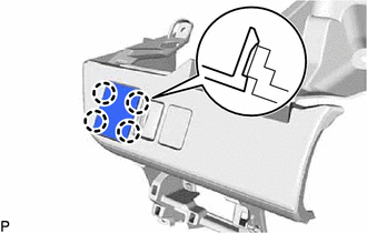
Engage the 4 claws to install the remote control mirror hole cover.
-
-
INSTALL NO. 1 INSTRUMENT PANEL SAFETY PAD (w/o Knee Airbag)
-
Engage the 2 claws and install the No. 1 instrument panel safety pad.
-
-
INSTALL NO. 2 INSTRUMENT PANEL SAFETY PAD (w/o Knee Airbag)
-
Engage the 2 claws and install the No. 2 instrument panel safety pad.
-