UPPER INSTRUMENT PANEL REMOVAL
CAUTION / NOTICE / HINT
Tech Tips
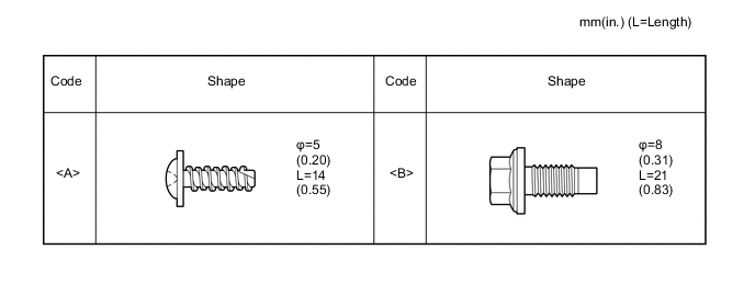
All bolts, screws and nuts relevant to installing and removing the instrument panel are shown, along with their alphabetic codes, in the table below.
PROCEDURE
-
PRECAUTION
Note
After turning the ignition switch off, waiting time may be required before disconnecting the cable from the negative (-) auxiliary battery terminal. Therefore, make sure to read the disconnecting the cable from the negative (-) auxiliary battery terminal notices before proceeding with work Click here.
-
REMOVE FRONT FLOOR COVER RH (for Front Floor Cover Type A)
-
REMOVE CENTER FRONT FLOOR COVER (for Front Floor Cover Type B)
-
REMOVE FRONT FLOOR COVER RH (for Front Floor Cover Type B)
-
DISCONNECT CABLE FROM NEGATIVE AUXILIARY BATTERY TERMINAL
Note
When disconnecting the cable, some systems need to be initialized after the cable is reconnected ( Click here).
-
REMOVE FRONT DOOR SCUFF PLATE RH
-
REMOVE FRONT DOOR SCUFF PLATE LH
Tech Tips
Use the same procedure as for the RH side.
-
REMOVE COWL SIDE TRIM BOARD RH
-
REMOVE COWL SIDE TRIM BOARD LH
Tech Tips
Use the same procedure as for the RH side.
-
SEPARATE FRONT DOOR OPENING TRIM WEATHERSTRIP RH
-
Separate the front door opening trim weatherstrip.
-
-
SEPARATE FRONT DOOR OPENING TRIM WEATHERSTRIP LH
-
Separate the front door opening trim weatherstrip.
-
-
REMOVE FRONT PILLAR GARNISH RH (w/ Curtain Shield Airbag)
-
REMOVE FRONT PILLAR GARNISH LH (w/ Curtain Shield Airbag)
Tech Tips
Use the same procedure as for the RH side.
-
REMOVE FRONT PILLAR GARNISH RH (w/o Curtain Shield Airbag)
-
REMOVE FRONT PILLAR GARNISH LH (w/o Curtain Shield Airbag)
Tech Tips
Use the same procedure as for the RH side.
-
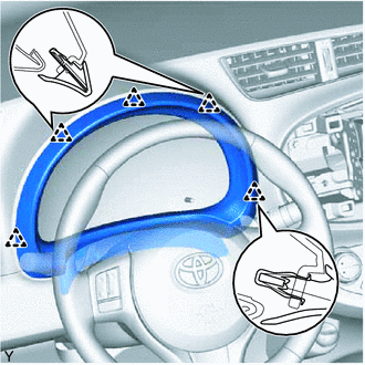
REMOVE INSTRUMENT CLUSTER FINISH PANEL GARNISH ASSEMBLY
-
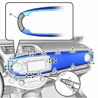
Disengage the 10 clips and the 4 guides and remove the instrument cluster finish panel garnish.
Tech Tips
Disengage the clips in order starting from the outside of the vehicle.
Note
To prevent parts from breaking, do not pull on section A when disengaging the clips.
-
-
REMOVE NO. 4 INSTRUMENT PANEL REGISTER ASSEMBLY (for Front Passenger Side)
-
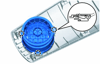
Disengage the 3 claws and remove the instrument panel register.
-
-
REMOVE INSTRUMENT CLUSTER FINISH CENTER PANEL SUB-ASSEMBLY (w/o Radio Receiver)
-
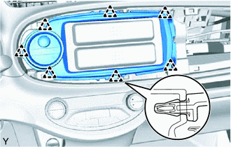
Disengage the 7 clips.
-
Disconnect the connector and remove the instrument cluster finish center panel.
-
-
REMOVE INSTRUMENT CLUSTER FINISH CENTER PANEL SUB-ASSEMBLY (w/ Radio Receiver)
-
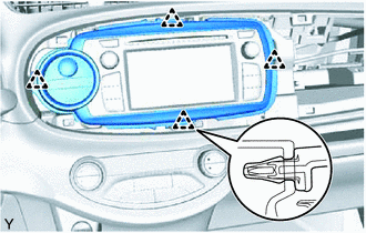
Disengage the 4 clips.
-
Disconnect the connector and remove the instrument cluster finish center panel.
-
-
REMOVE NO. 1 INSTRUMENT CLUSTER FINISH PANEL
-
Disengage the 5 clips and remove the instrument cluster finish panel.
-
-
REMOVE COMBINATION METER ASSEMBLY
-
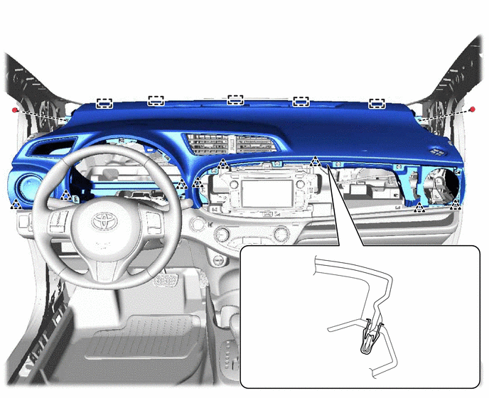
REMOVE UPPER INSTRUMENT PANEL SUB-ASSEMBLY
-
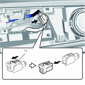
Text in Illustration *1 Slider Slide the slider and disconnect the passenger airbag connector.
-
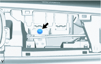
Remove the <B> bolt.
-
Remove the 2 clips.
-
Disengage the 8 clips while lifting the rear instrument panel up.
-
While lifting the instrument panel, slide it toward the rear of the vehicle. Disengage the 5 guides of the front side of the instrument panel and remove the upper instrument panel.
Note
Be careful not to damage the upper instrument panel and steering wheel when removing it.
-