SOLAR SENSOR INSPECTION
PROCEDURE
-
INSPECT SOLAR SENSOR (AUTOMATIC LIGHT CONTROL SENSOR) (w/ Automatic Light Control System)
-
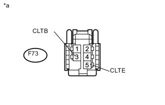
Text in Illustration *a Front view of wire harness connector
(to Solar Sensor)
Disconnect the F73 solar sensor connector.
-
Measure the voltage according to the value(s) in the table below.
Standard Voltage Tester Connection Switch Condition Specified Condition F73-3 (CLTB) - F73-5 (CLTE) Ignition switch off Below 1 V F73-3 (CLTB) - F73-5 (CLTE) Ignition switch ON 11 to 14 V -
Reconnect the solar sensor connector.
-
Turn the ignition switch to ON.
-
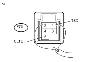
Text in Illustration *a Component with harness connected
(Solar Sensor)
Measure the voltage according to the value(s) in the table below.
Standard Voltage Tester Connection Condition Specified Condition F73-1(TSD) - F73-5(CLTE) Without direct light exposure (Sensor covered) Below 0.8 V F73-1(TSD) - F73-5(CLTE) When exposed to sunlight or an inspection light 4.0 to 4.6 V Note
Use an incandescent light for inspection. Bring it within about 30 cm (11.8 in.) of the solar sensor.
If the result is not as specified, replace the solar sensor.
-
-
INSPECT SOLAR SENSOR (COOLER THERMISTOR) (w/o Automatic Light Control System)
-
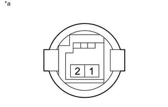
Text in Illustration *a Component without harness connected
(Solar Sensor)
Connect the positive (+) lead from the ohmmeter to terminal 1 and the negative (-) lead to terminal 2 of the solar sensor.
-
Measure the resistance according to the value(s) in the table below.
Standard Resistance Tester Connection Condition Specified Condition 1 - 2 Without direct light exposure (Sensor covered) ∞ Ω 1 - 2 When exposed to sunlight or an inspection light Except ∞ Ω Note
The connection procedure for using a digital tester such as an electrical tester is shown above. When using an analog tester, connect the positive (+) lead to terminal 2 and the negative (-) lead to terminal 1 of the solar sensor.
Tech Tips
-
As the inspection light is moved away from the sensor, the voltage decreases.
-
Use an incandescent light for the inspection. Position it about 30 cm (11.8 in.) from the solar sensor.
If the result is not as specified, replace the cooler thermistor.
-
-