LOWER INSTRUMENT PANEL REMOVAL
CAUTION / NOTICE / HINT
Tech Tips
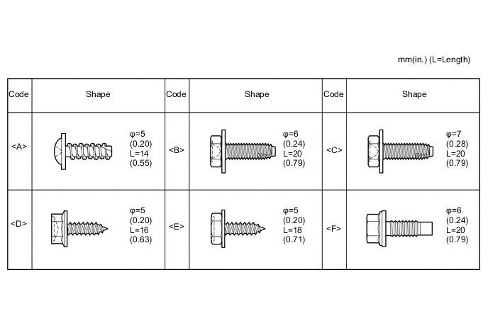
All bolts, screws and nuts relevant to installing and removing the instrument panel are shown, along with their alphabetic codes, in the table below.
PROCEDURE
-
REMOVE UPPER INSTRUMENT PANEL SUB-ASSEMBLY
-
REMOVE FRONT DOOR SCUFF PLATE RH
-
REMOVE FRONT DOOR SCUFF PLATE LH
Tech Tips
Use the same procedure as for the RH side.
-
REMOVE COWL SIDE TRIM BOARD RH
-
REMOVE COWL SIDE TRIM BOARD LH
Tech Tips
Use the same procedure as for the RH side.
-
REMOVE GLOVE COMPARTMENT DOOR ASSEMBLY
-
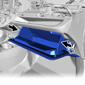
Disengage the claw to separate the glove compartment door stopper sub-assembly from the glove compartment door assembly.
-
Slightly flex the upper part of the glove compartment door assembly to release the 2 stoppers and open the glove compartment door assembly until it is horizontal.
-
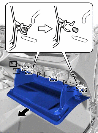
Text in Illustration *a Hinge *b Guide Pull the glove compartment door assembly out horizontally to disengage the 2 hinges and 3 guides to remove the glove compartment door assembly.
Note
Pull the glove compartment door assembly out horizontally. Otherwise, the hinge may be damaged, making re-installation impossible.
-
-
REMOVE NO. 2 INSTRUMENT PANEL UNDER COVER SUB-ASSEMBLY
-
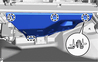
Disengage the 3 claws and guide to remove the No. 2 instrument panel under cover sub-assembly.
-
w/ Footwell Light:
-
Disconnect the connector.
-
-
-
REMOVE NO. 1 INSTRUMENT PANEL UNDER COVER SUB-ASSEMBLY
-
Remove the 2 <A> screws.
-
Disengage the 2 claws and guide to remove the No. 1 instrument panel under cover sub-assembly.
-
w/ Footwell Light:
-
Disconnect the connector.
-
-
-
REMOVE LOWER NO. 2 INSTRUMENT PANEL FINISH PANEL
-
for LHD:
-
w/o Pre-crash Safety System:
-
Disengage the 5 clips, 2 claws and guide to remove the No. 2 instrument panel finish panel.
-
-
w/ Pre-crash Safety System:
-
Disengage the 6 clips and 2 claws to remove the No. 2 instrument panel finish panel.
-
Disconnect the connectors.
-
-
-
for RHD:
-
Disengage the 6 clips and 2 claws to remove the No. 2 instrument panel finish panel.
-
w/ Pre-crash Safety System:
-
Disconnect the connectors.
-
-
-
-
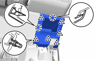
REMOVE LOWER INSTRUMENT PANEL FINISH PANEL (w/o Knee Airbag)
-
for LHD:
-
Disengage the 2 clips and 5 claws to remove the lower instrument panel finish panel
-
-
for RHD:
-
Disengage the 2 clips and 6 claws to remove the lower instrument panel finish panel.
-
-
-
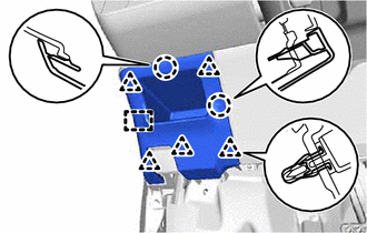
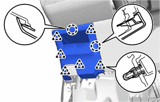
REMOVE LOWER NO. 1 INSTRUMENT PANEL AIRBAG ASSEMBLY (w/ Knee Airbag)
-
REMOVE STEREO OPENING COVER WITH BRACKET (w/o Radio Receiver)
-
Remove the 4 screws and stereo opening cover with bracket.
-
-
REMOVE RADIO RECEIVER ASSEMBLY WITH BRACKET (w/ Radio Receiver)
-
REMOVE AIR CONDITIONING CONTROL ASSEMBLY
-
REMOVE NO. 1 STEREO JACK ADAPTER ASSEMBLY (w/o Cover)
-
REMOVE SPARE SWITCH HOLE COVER (w/ Cover)
-
Disengage the 2 claws to remove the spare switch hole cover.
-
-
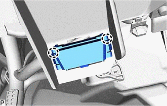
REMOVE NO. 1 POWER OUTLET SOCKET ASSEMBLY (w/ Power Outlet Socket)
-
REMOVE NO. 1 POWER OUTLET SOCKET COVER (w/ Power Outlet Socket)
-
REMOVE CIGARETTE LIGHTER ASSEMBLY (w/ Cigarette Lighter)
-
REMOVE CIGARETTE LIGHTER BEZEL STAY (w/ Cigarette Lighter)
-
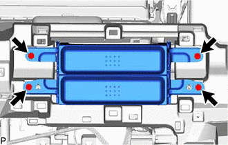
REMOVE REAR CONSOLE BOX ASSEMBLY
-
SEPARATE HOOD LOCK CONTROL LEVER SUB-ASSEMBLY
-
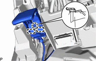
Disengage the claw and 2 guides to separate the hood lock control lever sub-assembly.
-
-
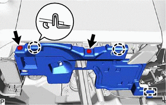
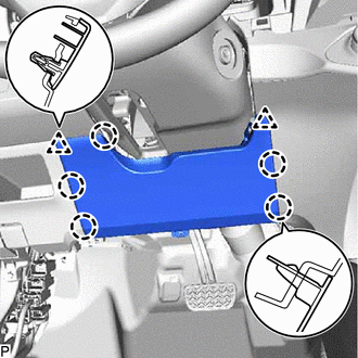
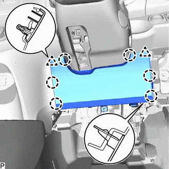
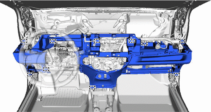
REMOVE LOWER INSTRUMENT PANEL SUB-ASSEMBLY
-
Disengage the 2 claws to disconnect the DLC3 connector.
-
Disengage the clamps.
-
Disconnect the connectors.
-
Remove the 6 <B> or <C> bolts, <D> or <E> screw and 2 <F> bolts from the lower instrument panel sub-assembly.
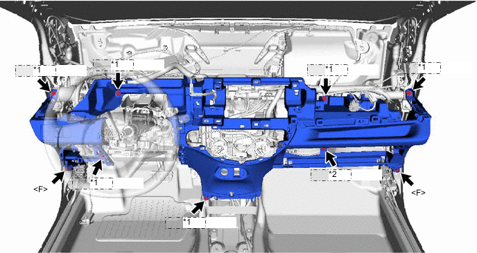
*1 <B> or <C> *2 <D> or <E> -
Disengage the 10 guides to remove the lower instrument panel sub-assembly.
-