AIR CONDITIONING SYSTEM SYSTEM DESCRIPTION
-
GENERAL
-
The air conditioning system has the following features:
-
In accordance with the temperature set using the temperature control switch, the air conditioning amplifier determines the outlet temperature based on the input signals from various sensors. In addition, corrections are added in accordance with the signals from the water temperature sensor to control the outlet air temperature.
-
Controls the blower motor in accordance with the airflow volume determined by the air conditioning amplifier based on the input signals from various sensors.
-
Automatically changes the outlets in accordance with the outlet mode ratio that is determined by the air conditioning amplifier based on the input signals from various sensors.
-
Checks the sensors in accordance with the operations of the air conditioner switches.
-
The air conditioning amplifier has the function of controlling the indicator lighting.
-
-
-
MODE POSITION AND DAMPER OPERATION
-
Mode position and damper operation
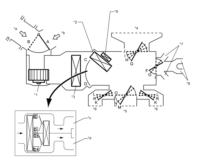
Text in Illustration *1 Blower Motor with Fan Sub-Assembly *2 Heater Radiator Unit Sub-Assembly *3 No. 1 Cooler Evaporator Sub-Assembly *4 Front Defroster *5 Center Register *6 Side Register *7 Front Footwell Register Duct *8 Rear Footwell Register Duct *9 Quick Heater Assembly - - *a Fresh Air *b Recirculated Air *c to Driver Side *d to Front Passenger Side Tech Tips
This illustration shows damper operation. The number and location of the dampers is different from the actual unit.
Functions of Main Dampers Control Damper Control Position Damper Position Operation Air Inlet Control Damper FRESH A Allows outside air to enter. RECIRC B Recirculates internal air. Air Mix Control Damper MAX COLD to MAX HOT Temperature Setting C, D
C1, D1
Continuously changes mix ratio of warm and cool air between COOL and HOT. Mode Control Damper FACE

M, L, E, J Blows air from center register and side registers. BI - LEVEL

N, R, F, J Blows air from center register, side registers, front footwell register and rear footwell register. FOOT

O, K, F, I Blows air from side registers, front footwell register and rear footwell register. Also, blows some air from front defroster. FOOT / DEF

O, K, G, H Blows air from front defroster, side registers, front footwell register and rear footwell registers. DEF

O, R, E, Q Blows air from front defroster and side register.
-
-
AIR OUTLET AND AIRFLOW VOLUME
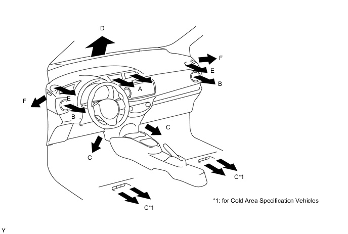
Air Outlet Mode Air Outlet Position Symbol A B C D E F Center Face Side Face Foot Defroster Side Defroster Side Defroster FACE 
- - - - BI - LEVEL 
- - - FOOT - 
FOOT/DEF - 
DEF - - The size of the circle ○ indicates the proportion of airflow volume.