REAR SEAT OUTER BELT ASSEMBLY INSTALLATION

CAUTION / NOTICE / HINT
Note
Some of these service operations affect the SRS airbag system. Read the precautionary notices concerning the SRS airbag system before servicing Click here.
Tech Tips
-
Use the same procedure for the RH and LH side.
-
The procedure listed below is for the LH side.
PROCEDURE
-
INSTALL SEAT BELT HOLE SEAL
-
Engage the 2 claws to install the seat belt hole seal.
-
-
INSTALL REAR SEAT 3 POINT TYPE OUTER BELT ASSEMBLY
-
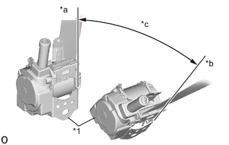
*1 Retractor *a Unlock *b Lock *c 45° Check the angle of inclination required to lock the retractor.
-
Gently incline the retractor from its initial position. Check that the belt does not lock when the retractor is inclined 15° or less in any direction. Also, check that the belt locks when the inclination of the retractor is 45° or more.
Note
Do not disassemble the retractor.
If the operation is not as specified, replace the rear seat 3 point type outer belt assembly.
-
-
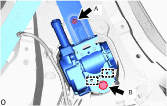
Engage the 2 hooks and temporarily install the rear seat 3 point type outer belt assembly with the 2 bolts.
-
Tighten bolt A and then bolt B.
- Torque:
- for bolt A
- 12.5 N*m { 127 kgf*cm, 9 ft.*lbf }
- for bolt B
- 42 N*m { 428 kgf*cm, 31 ft.*lbf }
-
Connect the shoulder anchor with the bolt.
- Torque:
- 42 N*m { 428 kgf*cm, 31 ft.*lbf }
-
Connect the floor anchor with the bolt.
- Torque:
- 42 N*m { 428 kgf*cm, 31 ft.*lbf }
-
Check that the ELR locks.
Note
-
The check should be performed with the rear seat 3 point type outer belt assembly installed.
-
Do not allow the anchor part of the rear seat 3 point type outer belt assembly and the protruding parts of the floor panel to overlap.
-
With the belt installed, check that the belt locks when it is pulled out quickly.
If the operation is not as specified, replace the rear seat 3 point type outer belt assembly.
-
-
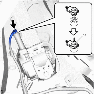
*a Locking Button Connect the pretensioner connector.
-
Lock the locking button.
Note
Securely lock the locking button.
-
Remove the bolt to disconnect the floor anchor.
-
-
INSTALL ROOF SIDE INNER GARNISH
-
INSTALL DECK TRIM SIDE PANEL ASSEMBLY RH (for RH Side)
-
INSTALL DECK TRIM SIDE PANEL ASSEMBLY LH (for LH Side)
-
CONNECT REAR SEAT 3 POINT TYPE OUTER BELT ASSEMBLY
-
CONNECT REAR DOOR OPENING TRIM WEATHERSTRIP
-
Connect the rear door opening trim weatherstrip.
-
-
INSTALL REAR DOOR SCUFF PLATE
-
INSTALL JACK HANDLE (for RH Side)
-
INSTALL NO. 1 LUGGAGE COMPARTMENT LIGHT ASSEMBLY (for LH Side)
-
INSTALL REAR FLOOR FINISH PLATE
-
INSTALL SPARE WHEEL COVER (w/ Cover)
-
INSTALL DECK BOARD ASSEMBLY (w/ Deck Board)
-
CONNECT CABLE TO NEGATIVE AUXILIARY BATTERY TERMINAL
- Torque:
- 5.4 N*m { 55 kgf*cm, 48 in.*lbf }
Note
When disconnecting the cable, some systems need to be initialized after the cable is reconnected Click here.
-
INSTALL FRONT FLOOR COVER LH (for Front Floor Cover Type A)
-
INSTALL FRONT FLOOR COVER RH (for Front Floor Cover Type A)
-
INSTALL FRONT FLOOR COVER LH (for Front Floor Cover Type B)
-
INSTALL FRONT FLOOR COVER RH (for Front Floor Cover Type B)
-
INSTALL CENTER FRONT FLOOR COVER (for Front Floor Cover Type B)
-
INSTALL REAR SEAT ASSEMBLY (for 60/40 Split Seat Type RH Side)
-
INSTALL REAR SEAT ASSEMBLY (for 60/40 Split Seat Type LH Side)
-
INSPECT SRS WARNING LIGHT