AIR CONDITIONING SYSTEM TERMINALS OF ECU
-
CHECK AIR CONDITIONING AMPLIFIER ASSEMBLY

Tech Tips
Check from the rear of the connector while it is connected to the air conditioning amplifier assembly.
Terminal No. (Symbol) Wiring Color Terminal Description Condition Specified Condition F29-1 (IG+) - F29-14 (GND) V - BR Power source (IG) Ignition switch ON (IG) 11 to 14 V F29-3 (PTC3) - F29-14 (GND)*1 V - BR Quick heater operation signal Ignition switch ON (READY) Below 1 V ECO switch assembly (ECO mode switch) off Blower motor on Temperature settings: MAX HOT Engine coolant temperature approximately 50°C lower Ambient temperature 10°C or lower IDH terminal signal less than 1 V (Inverter with converter assembly overload not detected) F29-4 (ECOS) - F29-14 (GND) R - BR ECO switch assembly (ECO mode switch) signal Ignition switch ON (IG) Below 1 V ECO switch assembly (ECO mode switch) on Ignition switch ON (IG) 11 to 14 V ECO switch assembly (ECO mode switch) off F29-5 (TAM) - F29-13 (SG-2) W - L A/C ambient temperature sensor signal Ignition switch ON (IG) at 25°C (77°F) 1.35 to 1.75 V F29-9 (PRE) - F29-14 (GND) GR - BR Air conditioning pressure sensor signal Ignition switch ON (READY) 0.63 to 4.73 V A/C system operating Refrigerant pressure: Normal Ignition switch ON (READY) Below 0.63 V or 4.73 V or more A/C system operating Refrigerant pressure: Abnormal (less than 0.176 MPaG [1.8 kgf/cm2]) or more than 3.03 MPaG [31 kgf/cm2])
F29-10 (S5-3) - F29-14 (GND) Y - BR Power supply for pressure sensor Ignition switch ON (IG) 4.75 to 5.25 V F29-11 (CANH) - F29-14 (GND) V - BR CAN communication signal Ignition switch ON (IG) Pulse generation
(See waveform 1)
F29-12 (CANL) - F29-14 (GND) W - BR CAN communication signal Ignition switch ON (IG) Pulse generation
(See waveform 2)
F29-13 (SG-2) - Body ground L - Body ground Ground for ambient temperature sensor and A/C pressure sensor Always Below 1 Ω F29-14 (GND) - Body ground BR - Body ground Ground for main power supply Always Below 1 Ω F29-21 (B) - F29-14 (GND) BE - BR Power source (Back-up) Always 11 to 14 V F29-22 (BLW) - F29-14 (GND) R - BR Blower motor control signal Ignition switch ON (IG) Pulse generation
(See waveform 3)
Blower switch: LO F29-27 (IDH) - F29-14 (GND)*1 L - BR Inverter with converter assembly current over signal Ignition switch ON (IG) (inverter with converter assembly overload not detected) Less than 1 V F29-29 (TR) - F29-34 (SG-1) P - SB Room temperature sensor signal Ignition switch ON (IG) 1.8 to 2.2 V Vehicle interior temperature: 25°C F29-30 (S5-4) - F29-14 (GND)*2 L - BR Solar sensor power supply Ignition switch ON (IG) 4.5 to 5.5 V F29-33 (TSD) - F29-14 (GND) R - BR Solar sensor signal Ignition switch ON (IG) 0.8 to 4.3 V Solar sensor subject to electric light F29-34 (SG-1) - Body ground SB - Body ground Ground for room temperature sensor Always Below 1 Ω F29-37 (LIN1) - F29-14 (GND) LG - BR LIN communication signal Ignition switch ON (IG) Pulse generation F29-39 (PTC2) - F29-14 (GND)*1 BR - BR Quick heater operation signal Ignition switch ON (READY) Below 1 V ECO switch assembly (ECO mode switch) off Blower motor on Temperature settings: MAX HOT Engine coolant temperature approximately 50°C lower Ambient temperature 10°C or lower IDH terminal signal less than 1 V (Inverter with converter assembly overload not detected) F29-40 (PTC1) - F29-14 (GND)*1 SB - BR Quick heater operation signal Ignition switch ON (READY) Below 1 V ECO switch assembly (ECO mode switch) off Blower motor on Temperature settings: MAX HOT Engine coolant temperature approximately 50°C or lower Ambient temperature 10°C or lower IDH terminal signal less than 1 V (Inverter with converter assembly overload not detected) z1-2 (BUS G) - Body ground - Ground for BUS IC Always Below 1 Ω z1-3 (BUS) - z1-2 (BUS G) - BUS IC control signal Ignition switch ON (IG) Pulse generation z1-4 (B BUS) - z1-2 (BUS G) - BUS IC power supply Always 11 to 14 V z1-5 (SGA) - Body ground - Ground for evaporator temperature sensor Always Below 1 Ω z1-6 (TEA) - z1-5 (SGA) - Evaporator temperature sensor signal Ignition switch ON (IG) 1.4 to 1.8 V Evaporator temperature: 15°C (59°F)
-
*1: w/ PTC Heater
-
*2: w/o Automatic Light Control System
If the result is not as specified, there may be a malfunction in the wire harness.
-
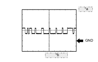
*a 1 V/DIV. *b 10 μsec./DIV. Waveform 1 (Reference) : Using an oscilloscope
CAN Communication Signal Terminal Name F29-11 (CANH) - F29-14 (GND) Tester Range 1 V/DIV, 10 μsec./DIV. Condition Ignition switch ON (IG) Tech Tips
The waveform varies depending on the CAN communication signal.
-
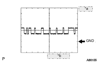
*a 1 V/DIV. *b 10 μsec./DIV. Waveform 2 (Reference) : Using an oscilloscope
CAN Communication Signal Terminal Name F29-12 (CANL) - F29-14 (GND) Tester Range 1 V/DIV, 10 μsec./DIV. Condition Ignition switch ON (IG) Tech Tips
The waveform varies depending on the CAN communication signal.
-
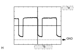
*a 1 V/DIV. *b 500 μsec/DIV. Waveform 3: Using an oscilloscope.
Blower Motor Control Signal Terminal Name F29-22 (BLW) - F29-14 (GND) Tester Range 1 V/DIV, 500 μsec./DIV. Condition Ignition switch ON (IG)
Blower switch LO
Tech Tips
When the blower level is increased, the duty ratio changes accordingly.
-
-
CHECK AIR CONDITIONING CONTROL ASSEMBLY

Terminal No. (Symbol) Wiring Color Terminal Description Condition Specified Condition F28-5 (IG+) - F28-8 (GND) V - BR Power source (IG) Ignition switch ON (IG) 11 to 14 V F28-3 (LIN1) - F28-8 (GND) LG - BR LIN communication signal Ignition switch ON (IG) Pulse generation F28-8 (GND) - Body ground BR - Body Ground Ground for air conditioning control assembly Always Below 1 Ω If the result is not as specified, there may be a malfunction in the wire harness.
-
HYBRID VEHICLE CONTROL ECU Click here
-
INVERTER WITH CONVERTER ASSEMBLY Click here